Pulse width modulation (PWM) is not only used in communication systems but also used in high current driving applications like motor drivers, LED drivers, etc.
In PIC MCU the PWM is a common peripheral and some version of PIC MCU has more than on the PWM module. The PWM peripheral is used to generate a digital signal with a user-defined period. Also, the user can configure the duty cycle (“ON” time) that can be used to encode a message or control the amount of power supplied to electrical devices.
The main aim of this blog post to describe how we can use the inbuilt PWM of the PIC microcontroller. I have also written a blog post on how to control the dc motor with PIC MCU using the PWM, if you want you can read.
What is pulse width modulation (PWM)?
PWM is a way to use a digital output to vary the on, or high time, to create a variable output or square wave. If the PWM signal runs at a fixed frequency, then changing the high time of the signal will also change the low time of the signal.
The amount of time the signal remains high is typically called the pulse width. That pulse width relative to the period of the signal is called the duty cycle.
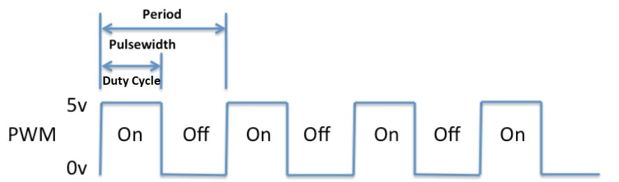
The period of the signal is defined as the time from one rising edge to the next rising edge of the square wave signal and is inversely proportional to the PWM frequency.
The period can easily be calculated by using the formula:
Period = 1/Frequency.
For example, if the frequency is 1 kHz, the period will be 1 millisecond.
We can also define the duty cycle using the below formula,
Duty cycle = ( ON/ (ON + OFF) ) x 100 percentage

PWM in PIC Microcontroller:
The PIC Microcontroller has an inbuilt CCP module and PWM can be easily generated using the inbuilt CCP module. CCP stands for Capture/Compare/PWM. CCP modules are available with a number of PIC Microcontrollers. Most of them have more than one CCP module.
Here, I am referring to PIC16F877A that has 2 CCP modules, named CCP1 and CCP2. Each Capture/Compare/PWM (CCP) module contains a 16-bit register which can operate as a:
- 16-bit Capture Register.
- 16-bit Compare Register.
- PWM Master/Slave Duty Cycle register
Note: The timer resource for PWM in PIC16F877A is Timer2.
PIC16F877A PWM Registers
Before using the PWM, I want to introduce some registers which will be used in the PWM configuration. The below table shows the registers associated with PIC16F877A PWM.
| Register | Description |
|---|---|
| CCPxCON | This register is used to Configure the CCP module for Capture/Compare/PWM operation and store 2 LSBs of the duty cycle. |
| CCPRxL | This register holds the 8-MSB bits of PWM, lower 2-bits will be part of the CCPxCON register which I have already described in the above table. |
| TMR2 | The free-running counter will be compared with CCPR1L and PR2 for generating the PWM output. |
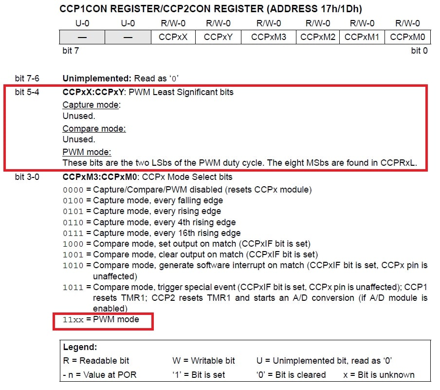
CCPxCON:
PIC16F87XA has two registers CCP1CON and CCP2CON. The CCP1CON register controls the operation of CCP1 and The CCP2CON register controls the operation of CCP2. You can see the below image of CCPxCON, where bit0 to bit3 is used to select the PWM mode, and bit4 and bit5 used to store the two LSbs bit of duty cycle.
CCPRxL:
The PWM duty cycle is specified by writing to the CCPR1L register and to the CCP1CON<5:4> bits (Up to 10-bit resolution). The CCPR1L contains the eight MSbs and the CCP1CON<5:4> contains the two LSbs. This 10-bit value is represented by CCPR1L:CCP1CON<5:4>.
PWM Duty Cycle = (CCPR1L:CCP1CON<5:4>) • TOSC • (TMR2 Prescale Value)
Where,
Oscillator frequency is defined as 1/TOSC.
You can check the Below book for a basic understanding of PIC Microcontroller and Embedded Systems: Using Assembly and C for PIC 18.
Check It:
Steps to Configure PWM
The following steps should be taken when configuring the CCP module for PWM operation. Here I am using the CCP1 module.
1. Configure the CCP1 module for PWM operation:
We can configure the PWM mode using the CCP1CON register.
//PWM mode ( CCP1M3:CCP1M0 = 11xx)

CCP1CON |= 0x0C;


x = Bit is unknown, Here I am assuming 0
2. Set the PWM period by writing to the PR2 register:
//Formula to calculate the value of the period register.

PR2 = ((Fosc)/(4∗TMR2Prescale∗PWMFrequency))−1
For example, we use a 20MHz clock and the o/p frequency is 5KHz and TMR2 Prescale is 4.
PR2 = [(20000000)/(4∗4∗5000 )]−1
PR2 = 250 – 1
PR2 = 249
PR2 = 0xF9 ( 249 in hex)
3. Set the PWM duty cycle by writing to the CCPR1L register and CCP1CON<5:4> bits.
//Calculate the value of registers
//CCPR1L and CCP1CON<5:4> for the given duty cycle.


(CCPR1L:CCP1CON<5:4>) = PWM Duty Cycle / (TOSC * (TMR2 Prescale Value));
Where,
Oscillator frequency is defined as 1/TOSC.
Q):- Calculate the value of PR2 and CCPR1L:CCP1CON<5:4> to generate PWM waveform of 1Khz frequency with 25%,50%,75%,100% Duty cycle using PWM1. Assume XTAL= 4 MHz and Prescaler = 4.
Solution :-
Given XTAL= = fosc i.e. 4 MHz
Prescaler i.e. N = 4
fpwm = 1 KHz
Duty cycle => 25%
a) Value to be loaded in Period Register2 (PR2) = [ (fOSC ) / 4X fPWM x N ] -1 = 249 = 0xF9;
b) CCPR1L:CCP1CON<5:4>
i) Value to be loaded in Duty cycle register (CCPR1L) = %Duty Cycle x PR2 Value
= 0.25 x 249
= 62.25
= 62 Integer value {0.25 value after decimal point will be loaded by Duty cycle bits from CCP1CON Register}
CCPR1L = 62 = 3E;
ii) Value to be loaded in CCP1CON = 0x1C // 0.25 value after decimal point , PWM mode of operation of CCP module
Duty cycle => 50%
a) Value to be loaded in Period Register2 (PR2) = [ (fOSC ) / 4X fPWM x N ] -1 = 249 = 0xF9;
b) CCPR1L:CCP1CON<5:4>
i) Value to be loaded in Duty cycle register (CCPR1L) = %Duty Cycle x PR2 Value
= 0.5 x 249
= 124.50
= 124 Integer value {0.5 value after decimal point will be loaded by Duty cycle bits from CCP1CON Register}
CCPR1L = 124 = 7C;
ii) Value to be loaded in CCP1CON = 0x2C // 0.5 value after decimal point , PWM mode of operation of CCP module.
Duty cycle => 75%
a) Value to be loaded in Period Register2 (PR2) = [ (fOSC ) / 4X fPWM x N ] -1 = 249 = 0xF9;
b) CCPR1L:CCP1CON<5:4>
i) Value to be loaded in Duty cycle register (CCPR1L) = %Duty Cycle x PR2 Value
= 0.75 x 249
= 186.75
= 186 Integer value {0.75 value after decimal point will be loaded by Duty cycle bits from CCP1CON Register}
CCPR1L = 186= BA;
ii) Value to be loaded in CCP1CON = 0x3C // 0.75 value after decimal point , PWM mode of operation of CCP module.
Duty cycle => 100%
a) Value to be loaded in Period Register2 (PR2) = [ (fOSC ) / 4X fPWM x N ] -1 = 249 = 0xF9;
b) CCPR1L:CCP1CON<5:4>
i) Value to be loaded in Duty cycle register (CCPR1L) = %Duty Cycle x PR2 Value
= 1 x 249
= 249.00
= 249 Integer value {0.00 value after decimal point will be loaded by Duty cycle bits from CCP1CON Register}
CCPR1L = 249 = 0xFA;
ii) Value to be loaded in CCP1CON = 0x0C // 0.00 value after decimal point , PWM mode of operation of CCP module.
4. Since the CCP1 pin is multiplexed with the PORTC data latch, so make the CCP1 pin an output by clearing the TRISC<2> bit.
//Make the CCP1 pin an output by clearing the TRISC<2> bit

TRISC2 = 0; //Pwm
5.Set the TMR2 prescale value and enable Timer2 by writing to T2CON
//Configure T2CON for PWM

T2CON = 0x01;  // Set Prescaler to be 4

T2CON |= 0x04; // Enable the Timer2, hence enable the PWM.
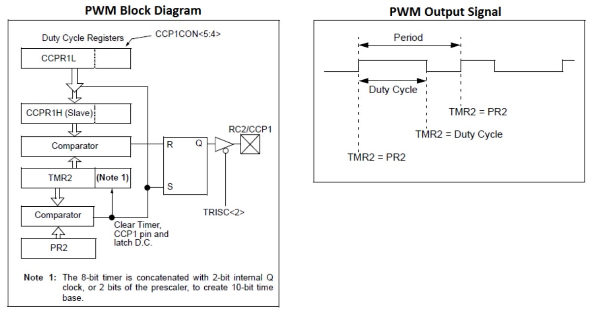
Working of PWM in CCP module:
You can see the below image to understand the working of the CCP module for the PWM. In the CCP module, CCPR1H is a read-only register.
The CCPR1H register and a 2-bit internal latch are used to double-buffer the PWM duty cycle. This double-buffering is essential for glitch-free PWM operation. When the CCPR1H and 2-bit latch match TMR2, the CCP1 pin is cleared.
When TMR2 is equal to PR2, the following three events occur on the next increment cycle, See the PWM Output Signal.
- TMR2 is cleared.
- The CCP1 pin is set (exception: if PWM duty cycle = 0%, the CCP1 pin will not be set).
- The PWM duty cycle is latched from CCPR1L into CCPR1H.
C code to generate PWM 1khz using PIC Microcontroller:
Let’s see a C program for the PIC microcontroller, where we are generating the PWM using the CCP1 module. The oscillator frequency is 4 Mhz, PWM is 1.00kHz, Prescaler value is 4, and duty cycle 25%.
/* Name     : main.c
*  Purpose  : Generating the PWM with PIC16F87XA.
*  Author   : Amlendra Kumar
*  Website  : https://aticleworld.com
*/

#define _XTAL_FREQ 4000000
#define TMR2PRESCALE 4
#include <xc.h>
#include<stdint.h>
// BEGIN CONFIG
#pragma config FOSC = HS // Oscillator Selection bits (HS oscillator)
#pragma config WDTE = OFF // Watchdog Timer Enable bit (WDT enabled)
#pragma config PWRTE = OFF // Power-up Timer Enable bit (PWRT disabled)
#pragma config BOREN = ON // Brown-out Reset Enable bit (BOR enabled)
#pragma config LVP = OFF // Low-Voltage (Single-Supply) In-Circuit Serial Programming Enable bit (RB3 is digital I/O, HV on MCLR must be used for programming)
#pragma config CPD = OFF // Data EEPROM Memory Code Protection bit (Data EEPROM code protection off)
#pragma config WRT = OFF // Flash Program Memory Write Enable bits (Write protection off; all program memory may be written to by EECON control)
#pragma config CP = OFF // Flash Program Memory Code Protection bit (Code protection off)
//END CONFIG

void main()
{
    TRISC=0x00;   ///RC2 pin as PWM output pin

    PR2= 0xF9;      ////PR2=(Fosc/4xNxFpwm)

    T2CON=0X01;  ///Prescaler=4

    TMR2=0x00;               //load TMR2=00H

    CCPR1L= 0x3E;       //25% Duty cycle

    CCP1CON=0X1C;    ///PWM mode, DCB1:DCB0=0.25 Decimal points

    T2CON |= 0x04; // Enable the Timer2, hence enable the PWM.

    while(1)      ///forever loop
    {

    }
}
Recommended Post:
- Interfacing DC motor with PIC Microcontroller using L293d
- Control DC Motor using the PIC Microcontroller and PWM.
- LED Interfacing with PIC Microcontroller.
- Best gift for programmers.
- Best electronic kits for programmers.
- Read and Write to Internal EEPROM of PIC Microcontroller.
- Best mouse for programming and coding
- Interfacing EEPROM with PIC Microcontroller – I2C Based.
- Interfacing RTC DS1307 with PIC Microcontroller.
- Display Custom Characters on LCD using PIC Microcontroller.
- PIC microcontroller tutorials.
- Led Blinking program in c for 8051.
- 8051 Microcontroller Pin Diagram and Pin Description.
- 8051 Architecture.