
In this blog post, we will learn 4×4 keypad interfacing with PIC Microcontroller. A keypad interfacing with PIC Microcontrollers is interesting. A keypad is an organized matrix of switches in rows and columns and it comes in the various form like a numeric keypad, alphanumeric keypad. It also comes in different sizes like 4×3, 4×4, etc.
Here I assumed you already know how to interface LCD with PIC Microcontroller. If you don’t know so it is my request first read my another article How to interface 16×2 LCD in 4-bit mode with PIC Microcontroller.
LCD and Keypad interfacing with PIC Microcontroller:
LCD is used as an output device and keypad as an input device. When the user presses the keypad key it will display on LCD.
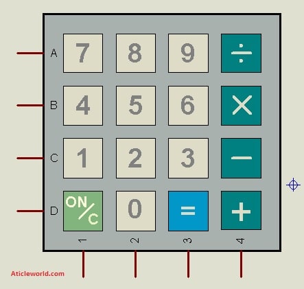
4×4 keypad consists of 4 rows and 4 columns and each switch is placed between the rows and columns. A keypress establishes a connection between the corresponding row and column between which the switch is placed.
In order to read the keypress, we need to configure the rows as outputs and columns as inputs.
Columns are read after applying signals to the rows in order to determine whether or not a key is pressed and if pressed, which key is pressed.
In the below circuit, RD0, RD1, and RD4 to RD7 pins are used to interface LCD with PIC Microcontroller. 8 pins of PORTB are used to interface 4×4 keypad. 4 pins are used to attach columns and 4 pins are used to attach rows and scanning algorithm code is used to check for any pressed key.
The below code is written in such a way that when you press any key from the keypad, then the value of that key is displayed on the LCD. I am interfacing LCD in 4-bit mode as I discuss in the previously to save the controller PIN if you want you can interface LCD in 8-bit mode. So let us see the C program,
/* Name     : main.c
*  Purpose  : Main file for keypad interfacing code for PIC16F877.
*  Author   : Amlendra Kumar
*  Website  : https://aticleworld.com
*/
#include<htc.h>

// Configuration word for PIC16F877A
__CONFIG( FOSC_HS & WDTE_OFF & PWRTE_ON & CP_OFF & BOREN_ON
          & LVP_OFF & CPD_OFF & WRT_OFF & DEBUG_OFF);


// Define CPU Frequency
// This must be defined, if __delay_ms() or
// __delay_us() functions are used in the code
#define _XTAL_FREQ   20000000


// Define Pins for LCD
#define LCD_E    			RD0     // Enable pin for LCD
#define LCD_RS	 			RD1     // RS pin for LCD
#define LCD_Data_Bus_D4		RD4		// Data bus bit 4
#define LCD_Data_Bus_D5		RD5		// Data bus bit 5
#define LCD_Data_Bus_D6		RD6		// Data bus bit 6
#define LCD_Data_Bus_D7		RD7		// Data bus bit 7

// Define Pins direction registrers
#define LCD_E_Dir     			TRISD0
#define LCD_RS_Dir   	 		TRISD1
#define LCD_Data_Bus_Dir_D4   	TRISD4
#define LCD_Data_Bus_Dir_D5     TRISD5
#define LCD_Data_Bus_Dir_D6  	TRISD6
#define LCD_Data_Bus_Dir_D7 	TRISD7

// Define which port is being used for data bus
#define LCD_PORT	PORTD

// Constants for delay
#define E_Delay       500


// Define pins for keypad
#define RowA		RB0
#define RowB		RB1
#define RowC		RB2
#define RowD		RB3
#define C1			RB4
#define C2			RB5
#define C3			RB6
#define C4			RB7

#define Keypad_PORT			PORTB
#define Keypad_PORT_Dir		TRISB


// Function Declarations for LCD
void WriteCommandToLCD(unsigned char);
void WriteDataToLCD(char);
void InitLCD(void);
void WriteStringToLCD(const char*);
void ClearLCDScreen(void);


// Function declarations for keypad
void InitKeypad(void);
char GetKey(void);


int main(void)
{
    char Key = 'n';		 // Variable to store pressed key value

    InitKeypad();		 // Initialize Keypad pins
    InitLCD();			 // Initialize LCD in 8bit mode
    WriteStringToLCD("Entered Key = ");
    while(1)
    {
        Key = GetKey();		 // Get pressed key from keypad
        ClearLCDScreen();	 // Clear LCD screen
        WriteStringToLCD("Entered Key = ");
        WriteDataToLCD(Key); //	Update LCD with current key value
    }
    return 0;
}


// Function name: InitKeypad
void InitKeypad(void)
{
    Keypad_PORT	    = 0x00;	// Set Keypad port pin values zero
    Keypad_PORT_Dir = 0xF0;	// Last 4 pins input, First 4 pins output

    // Enable weak internal pull up on input pins
    OPTION_REG &= 0x7F;
}


// Scan all the keypad keys to detect any pressed key.
char READ_SWITCHES(void)
{


  RowA = 0; RowB = 1; RowC = 1; RowD = 1; 	//Test Row A

  if (C1 == 0) { __delay_ms(250); while (C1==0); return '7'; }
  if (C2 == 0) { __delay_ms(250); while (C2==0); return '8'; }
  if (C3 == 0) { __delay_ms(250); while (C3==0); return '9'; }
  if (C4 == 0) { __delay_ms(250); while (C4==0); return '/'; }

  RowA = 1; RowB = 0; RowC = 1; RowD = 1; 	//Test Row B

  if (C1 == 0) { __delay_ms(250); while (C1==0); return '4'; }
  if (C2 == 0) { __delay_ms(250); while (C2==0); return '5'; }
  if (C3 == 0) { __delay_ms(250); while (C3==0); return '6'; }
  if (C4 == 0) { __delay_ms(250); while (C4==0); return 'x'; }

  RowA = 1; RowB = 1; RowC = 0; RowD = 1; 	//Test Row C

  if (C1 == 0) { __delay_ms(250); while (C1==0); return '1'; }
  if (C2 == 0) { __delay_ms(250); while (C2==0); return '2'; }
  if (C3 == 0) { __delay_ms(250); while (C3==0); return '3'; }
  if (C4 == 0) { __delay_ms(250); while (C4==0); return '-'; }

  RowA = 1; RowB = 1; RowC = 1; RowD = 0; 	//Test Row D

  if (C1 == 0) { __delay_ms(250); while (C1==0); return 'C'; }
  if (C2 == 0) { __delay_ms(250); while (C2==0); return '0'; }
  if (C3 == 0) { __delay_ms(250); while (C3==0); return '='; }
  if (C4 == 0) { __delay_ms(250); while (C4==0); return '+'; }

  return 'n';           	// Means no key has been pressed
}


// Function name: GetKey
// Read pressed key value from keypad and return its value
char GetKey(void)           	 // Get key from user
{
    char key = 'n';              // Assume no key pressed

    while(key=='n')              // Wait until a key is pressed
        key = READ_SWITCHES();   // Scan the keys again and again

    return key;                  //when key pressed then return its value
}


void ToggleEpinOfLCD(void)
{
    LCD_E = 1;                // Give a pulse on E pin
    __delay_us(E_Delay);      // so that LCD can latch the
    LCD_E = 0;                // data from data bus
    __delay_us(E_Delay);
}


void WriteCommandToLCD(unsigned char Command)
{
    LCD_RS = 0;				 	     // It is a command

    LCD_PORT &= 0x0F;		  		 // Make Data pins zero
    LCD_PORT |= (Command&0xF0);		 // Write Upper nibble of data
    ToggleEpinOfLCD();		   		 // Give pulse on E pin

    LCD_PORT &= 0x0F;		   		 // Make Data pins zero
    LCD_PORT |= ((Command<<4)&0xF0); // Write Lower nibble of data
    ToggleEpinOfLCD();		   		 // Give pulse on E pin
}


void WriteDataToLCD(char LCDChar)
{
    LCD_RS = 1;				 		 // It is data

    LCD_PORT &= 0x0F;			 	 // Make Data pins zero
    LCD_PORT |= (LCDChar&0xF0);  	 // Write Upper nibble of data
    ToggleEpinOfLCD();		 		 // Give pulse on E pin

    LCD_PORT &= 0x0F;		    	 // Make Data pins zero
    LCD_PORT |= ((LCDChar<<4)&0xF0); // Write Lower nibble of data
    ToggleEpinOfLCD();		 		 // Give pulse on E pin
}


void InitLCD(void)
{
    // Firstly make all pins output
    LCD_E  		 		 = 0;   // E  = 0
    LCD_RS  	 		 = 0;   // RS = 0
    LCD_Data_Bus_D4		 = 0;  	// Data bus = 0
    LCD_Data_Bus_D5		 = 0;  	// Data bus = 0
    LCD_Data_Bus_D6		 = 0;  	// Data bus = 0
    LCD_Data_Bus_D7		 = 0;  	// Data bus = 0
    LCD_E_Dir    		 = 0;   // Make Output
    LCD_RS_Dir    	 	 = 0;   // Make Output
    LCD_Data_Bus_Dir_D4  = 0;   // Make Output
    LCD_Data_Bus_Dir_D5  = 0;   // Make Output
    LCD_Data_Bus_Dir_D6  = 0;   // Make Output
    LCD_Data_Bus_Dir_D7  = 0;   // Make Output

    ///////////////// Reset process from data sheet //////////////
    __delay_ms(40);

    LCD_PORT &= 0x0F;		  // Make Data pins zero
    LCD_PORT |= 0x30;		  // Write 0x3 value on data bus
    ToggleEpinOfLCD();		  // Give pulse on E pin

    __delay_ms(6);

    LCD_PORT &= 0x0F;		  // Make Data pins zero
    LCD_PORT |= 0x30;		  // Write 0x3 value on data bus
    ToggleEpinOfLCD();		  // Give pulse on E pin

    __delay_us(300);

    LCD_PORT &= 0x0F;		  // Make Data pins zero
    LCD_PORT |= 0x30;		  // Write 0x3 value on data bus
    ToggleEpinOfLCD();		  // Give pulse on E pin

    __delay_ms(2);

    LCD_PORT &= 0x0F;		  // Make Data pins zero
    LCD_PORT |= 0x20;		  // Write 0x2 value on data bus
    ToggleEpinOfLCD();		  // Give pulse on E pin

    __delay_ms(2);
    /////////////// Reset Process End ////////////////
    WriteCommandToLCD(0x28);    //function set
    WriteCommandToLCD(0x0c);    //display on,cursor off,blink off
    WriteCommandToLCD(0x01);    //clear display
    WriteCommandToLCD(0x06);    //entry mode, set increment
}


void WriteStringToLCD(const char *s)
{
    while(*s)
        WriteDataToLCD(*s++);   // print first character on LCD
}


void ClearLCDScreen(void)       // Clear the Screen and return cursor to zero position
{
    WriteCommandToLCD(0x01);    // Clear the screen
    __delay_ms(2);              // Delay for cursor to return at zero position
}
Proteus Simulation of keypad interfacing with PIC Microcontroller:
Recommended Post:
- 16*2 LCD Interfacing with PIC Microcontroller in 4-bit Mode.
- 16*2 LCD Interfacing with PIC Microcontroller in 8-bit Mode.
- Push-button interfacing with PIC microcontroller.
- LED Interfacing with PIC Microcontroller.
- Read and Write to Internal EEPROM of PIC Microcontroller.
- Interfacing EEPROM with PIC Microcontroller – I2C Based.
- Interfacing RTC DS1307 with PIC Microcontroller.
- Display Custom Characters on LCD using PIC Microcontroller.
- Led blinking program in c for 8051.
- Interfacing of switch and led using the 8051
- Interfacing of Relay with 8051 microcontroller
- Moving message display on LCD using 8051
- LCD 4-bit mode c code for 8051.
- Create LCD custom characters for 16×2 alphanumeric LCD
- Interfacing of keypad with 8051
- Electronic digital lock using the 8051
- Interfacing of EEPROM with 8051 microcontrollers using I2C
- Embedded c interview questions.
- 8051 Microcontroller Pin Diagram and Pin Description.
- Can protocol interview questions.
- 8051 Architecture.