In this blog post, we will learn how to interface RTC DS1307 with PIC Microcontroller (PIC16F877A). RTC DS1307 connects with PIC Microcontroller using the I2C protocol. So here we will also see the I2C protocol implementation for PIC Microcontroller with the interfacing of 16X2 LCD.
You can see the below articles,
- Understanding of I2C protocol.
- How to interface LCD with 8051 microcontrollers.
- I2C interview Questions
So before seeing the code let us understand few concepts related to interfacing RTC DS1307 with PIC Microcontroller.
What is RTC?
A real-time clock (RTC) is a computer clock (most often in the form of an integrated circuit) that keeps track of the current time.
Although the term often refers to the devices in personal computers, servers, and embedded systems, RTCs are present in almost any electronic device which needs to keep accurate time.
What is I2C communication?
I2C is a serial communication protocol. It provides good support to the slow devices, for example, EEPROM, ADC, I2C LCD, and RTC, etc. It is not only used with the single board but also used with the other external components which have connected with boards through the cables.
I2C is basically a two-wire communication protocol. It uses only two-wire for communication. In which one wire is used for the data (SDA) and other wire is used for the clock (SCL).
In I2C, both buses are bidirectional, which means the master able to send and receive the data from the slave. The clock bus is controlled by the master but in some situations slave is also able to suppress the clock signal, but we will discuss it later.
Additionally, an I2C bus is used in the various control architecture, for example, SMBus (System Management Bus), PMBus (Power Management Bus), IPMI (Intelligent Platform Management Interface), etc.
DS1307 Basics
The Real-time clock DS1307 IC basically is a stand-alone time clock with the following features.
- Real-time clock (RTC) counts seconds, minutes, hours, date of the month, month, day of the week, and year with leap-year compensation valid up to 2100.
- The clock operates in either the 24-hour or 12-hour format with AM/PM indicator.
- 56-byte, battery-backed, non-volatile (NV) RAM for data storage
- Two-wire(I2C) serial interface
- Programmable squarewave output signal
- Automatic power-fail detect and switch circuitry
- Consumes less than 500nA in battery backup mode with oscillator running
- Optional industrial temperature range: -40°C to +85°C
Interfacing RTC DS1307 with PIC Microcontroller:
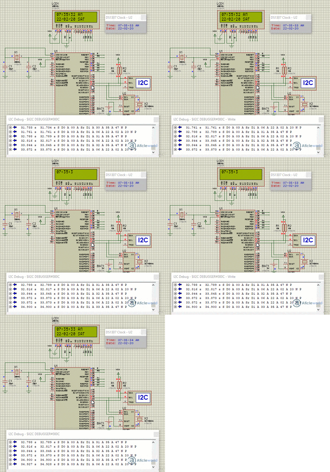
In the below circuit, the RC4 pin is being used as an SDA pin and the RC3 pin is the SCK pin. Both of these pins are pulled up using 10K resistors as required for i2c protocol. DS1307 RTC is the slave device, while PIC16F877 is configured to be the master.
LCD is also attached with PIC16F877, just to show the values received from the RTC. Proteus provides an ‘I2C Debugger Tool’ which is attached to the SDA and SCK pins in the above circuit, this debugger shows all the activity on the I2C bus. It is attached in the circuit just for debugging purposes.
In the code, at the start, the command is sent to DS1307 to set time to 7:34:59 AM and date to 22/02/20. After this, DS1307 starts to increment its time after every second. Then new time is read from DS1307 RTC after every second and displayed on the LCD.
/* Name     : main.c
*  Purpose  : Main file for DS1307 RTC interfacing with PIC16F877.
*  Author   : Amlendra Kumar
*  Website  : https://aticleworld.com
*/
#include<htc.h>

// Configuration word for PIC16F877A
__CONFIG( FOSC_HS & WDTE_OFF & PWRTE_ON & CP_OFF & BOREN_ON
          & LVP_OFF & CPD_OFF & WRT_OFF & DEBUG_OFF);


// Define CPU Frequency
// This must be defined, if __delay_ms() or
// __delay_us() functions are used in the code
#define _XTAL_FREQ   20000000


// Define i2c pins
#define SDA			RC4				// Data pin for i2c
#define SCK			RC3				// Clock pin for i2c
#define SDA_DIR		TRISC4			// Data pin direction
#define SCK_DIR		TRISC3			// Clock pin direction

// Define i2c speed
#define I2C_SPEED	100				// kbps

//Function Declarations
void InitI2C(void);
void I2C_Start(void);
void I2C_ReStart(void);
void I2C_Stop(void);
void I2C_Send_ACK(void);
void I2C_Send_NACK(void);
bit  I2C_Write_Byte(unsigned char);
unsigned char I2C_Read_Byte(void);


// Define Pins
#define LCD_E    			RB0     // Enable pin for LCD
#define LCD_RS	 			RB1     // RS pin for LCD
#define LCD_Data_Bus_D4		RB4		// Data bus bit 4
#define LCD_Data_Bus_D5		RB5		// Data bus bit 5
#define LCD_Data_Bus_D6		RB6		// Data bus bit 6
#define LCD_Data_Bus_D7		RB7		// Data bus bit 7

// Define Pins direction register
#define LCD_E_Dir     			TRISB0
#define LCD_RS_Dir   	 		TRISB1
#define LCD_Data_Bus_Dir_D4   	TRISB4
#define LCD_Data_Bus_Dir_D5     TRISB5
#define LCD_Data_Bus_Dir_D6  	TRISB6
#define LCD_Data_Bus_Dir_D7 	TRISB7

// Constants delay
#define E_Delay       500


// Function Declarations
void WriteCommandToLCD(unsigned char);
void WriteDataToLCD(char);
void InitLCD(void);
void WriteStringToLCD(const char*);
void ClearLCDScreen(void);
void DisplayTimeToLCD(unsigned char*) ;
void DisplayDateOnLCD( unsigned char*);


// Define DS1307 i2c device address
#define Device_Address_DS1307_EEPROM	0xD0

// Define Time Modes
#define AM_Time					0
#define PM_Time					1
#define TwentyFourHoursMode		2

// Define days
#define Monday		1
#define Tuesday		2
#define Wednesday	3
#define Thursday	4
#define Friday		5
#define Saturday	6
#define Sunday		7

// Function Declarations
void Write_Byte_To_DS1307_RTC(unsigned char, unsigned char);
unsigned char Read_Byte_From_DS1307_RTC(unsigned char);
void Write_Bytes_To_DS1307_RTC(unsigned char,unsigned char*,unsigned char);
void Read_Bytes_From_DS1307_RTC(unsigned char,unsigned char*,unsigned int);
void Set_DS1307_RTC_Time(unsigned char,unsigned char,unsigned char,unsigned char);
unsigned char* Get_DS1307_RTC_Time(void);
void Set_DS1307_RTC_Date(unsigned char,unsigned char,unsigned char,unsigned char);
unsigned char* Get_DS1307_RTC_Date(void);


// Global RTC Array and temp variable
unsigned char pRTCArray[4];
unsigned char Temp;


int main(void)
{
    InitLCD();	// Initialize LCD
    InitI2C();	// Initialize i2c pins

    // Set initial time
    Set_DS1307_RTC_Time(AM_Time,7, 34, 59);	// Set time 07:34:59 AM

    // Set initial date
    Set_DS1307_RTC_Date(22, 02,20, Saturday); 	// Set 22-02-2020 @ Saturday

    while(1)
    {
        // Display RTC time on first line of LCD
        DisplayTimeToLCD(Get_DS1307_RTC_Time());

        // Display RTC date on second line of LCD
        DisplayDateOnLCD(Get_DS1307_RTC_Date());

        __delay_ms(1000);	// 1 second delay
    }
    return 0;
}


//Function related to LCD

void ToggleEpinOfLCD(void)
{
    LCD_E = 1;                // Give a pulse on E pin
    __delay_us(E_Delay);      // so that LCD can latch the
    LCD_E = 0;                // data from data bus
    __delay_us(E_Delay);
}


void WriteCommandToLCD(unsigned char Command)
{
    LCD_RS = 0;				  // It is a command

    PORTB &= 0x0F;			  // Make Data pins zero
    PORTB |= (Command&0xF0);  // Write Upper nibble of data
    ToggleEpinOfLCD();		  // Give pulse on E pin

    PORTB &= 0x0F;			  // Make Data pins zero
    PORTB |= ((Command<<4)&0xF0); // Write Lower nibble of data
    ToggleEpinOfLCD();		  // Give pulse on E pin
}


void WriteDataToLCD(char LCDChar)
{
    LCD_RS = 1;				  // It is data

    PORTB &= 0x0F;			  // Make Data pins zero
    PORTB |= (LCDChar&0xF0);  // Write Upper nibble of data
    ToggleEpinOfLCD();		  // Give pulse on E pin

    PORTB &= 0x0F;			  // Make Data pins zero
    PORTB |= ((LCDChar<<4)&0xF0); // Write Lower nibble of data
    ToggleEpinOfLCD();		  // Give pulse on E pin
}


void InitLCD(void)
{
    // Firstly make all pins output
    LCD_E  		 		 = 0;   // E  = 0
    LCD_RS  	 		 = 0;   // RS = 0
    LCD_Data_Bus_D4		 = 0;  	// Data bus = 0
    LCD_Data_Bus_D5		 = 0;  	// Data bus = 0
    LCD_Data_Bus_D6		 = 0;  	// Data bus = 0
    LCD_Data_Bus_D7		 = 0;  	// Data bus = 0
    LCD_E_Dir    		 = 0;   // Make Output
    LCD_RS_Dir    	 	 = 0;   // Make Output
    LCD_Data_Bus_Dir_D4  = 0;   // Make Output
    LCD_Data_Bus_Dir_D5  = 0;   // Make Output
    LCD_Data_Bus_Dir_D6  = 0;   // Make Output
    LCD_Data_Bus_Dir_D7  = 0;   // Make Output

    ///////////////// Reset process from data sheet //////////////
    __delay_ms(40);

    PORTB &= 0x0F;			  // Make Data pins zero
    PORTB |= 0x30;			  // Write 0x3 value on data bus
    ToggleEpinOfLCD();		  // Give pulse on E pin

    __delay_ms(6);

    PORTB &= 0x0F;			  // Make Data pins zero
    PORTB |= 0x30;			  // Write 0x3 value on data bus
    ToggleEpinOfLCD();		  // Give pulse on E pin

    __delay_us(300);

    PORTB &= 0x0F;			  // Make Data pins zero
    PORTB |= 0x30;			  // Write 0x3 value on data bus
    ToggleEpinOfLCD();		  // Give pulse on E pin

    __delay_ms(2);

    PORTB &= 0x0F;			  // Make Data pins zero
    PORTB |= 0x20;			  // Write 0x2 value on data bus
    ToggleEpinOfLCD();		  // Give pulse on E pin

    __delay_ms(2);
    /////////////// Reset Process End ////////////////
    WriteCommandToLCD(0x28);    //function set
    WriteCommandToLCD(0x0c);    //display on,cursor off,blink off
    WriteCommandToLCD(0x01);    //clear display
    WriteCommandToLCD(0x06);    //entry mode, set increment
}


void WriteStringToLCD(const char *s)
{
    while(*s)
    {
        WriteDataToLCD(*s++);   // print first character on LCD
    }
}


void ClearLCDScreen(void)       // Clear the Screen and return cursor to zero position
{
    WriteCommandToLCD(0x01);    // Clear the screen
    __delay_ms(2);              // Delay for cursor to return at zero position
}


void DisplayTimeToLCD( unsigned char* pTimeArray )   // Displays time in HH:MM:SS AM/PM format
{
    ClearLCDScreen();      // Move cursor to zero location and clear screen

    // Display Hour
    WriteDataToLCD( (pTimeArray[2]/10)+0x30 );
    WriteDataToLCD( (pTimeArray[2]%10)+0x30 );

    //Display ':'
    WriteDataToLCD(':');

    //Display Minutes
    WriteDataToLCD( (pTimeArray[1]/10)+0x30 );
    WriteDataToLCD( (pTimeArray[1]%10)+0x30 );

    //Display ':'
    WriteDataToLCD(':');

    //Display Seconds
    WriteDataToLCD( (pTimeArray[0]/10)+0x30 );
    WriteDataToLCD( (pTimeArray[0]%10)+0x30 );

    //Display Space
    WriteDataToLCD(' ');

    // Display mode
    switch(pTimeArray[3])
    {
    case AM_Time:
        WriteStringToLCD("AM");
        break;
    case PM_Time:
        WriteStringToLCD("PM");
        break;

    default:
        WriteDataToLCD('H');
        break;
    }
}


void DisplayDateOnLCD( unsigned char* pDateArray )   // Displays Date in DD:MM:YY @ Day format
{
    WriteCommandToLCD(0xc0);      // Move cursor to second line

    // Display Date
    WriteDataToLCD( (pDateArray[1]/10)+0x30 );
    WriteDataToLCD( (pDateArray[1]%10)+0x30 );

    //Display '/'
    WriteDataToLCD('/');

    //Display Month
    WriteDataToLCD( (pDateArray[2]/10)+0x30 );
    WriteDataToLCD( (pDateArray[2]%10)+0x30 );

    //Display '/'
    WriteDataToLCD('/');

    //Display Year
    WriteDataToLCD( (pDateArray[3]/10)+0x30 );
    WriteDataToLCD( (pDateArray[3]%10)+0x30 );

    //Display Space
    WriteDataToLCD(' ');

    // Display Day
    switch(pDateArray[0])
    {
    case Monday:
        WriteStringToLCD("MON");
        break;
    case Tuesday:
        WriteStringToLCD("TUE");
        break;
    case Wednesday:
        WriteStringToLCD("WED");
        break;
    case Thursday:
        WriteStringToLCD("THU");
        break;
    case Friday:
        WriteStringToLCD("FRI");
        break;
    case Saturday:
        WriteStringToLCD("SAT");
        break;
    case Sunday:
        WriteStringToLCD("SUN");
        break;

    default:
        WriteStringToLCD("???");
        break;
    }
}


//Function related to I2C


// Function Purpose: Configure I2C module
void InitI2C(void)
{
    SDA_DIR = 1;		// Make SDA and
    SCK_DIR = 1;		// SCK pins input

    SSPADD  = ((_XTAL_FREQ/4000)/I2C_SPEED) - 1;
    SSPSTAT = 0x80;		// Slew Rate control is disabled
    SSPCON  = 0x28;		// Select and enable I2C in master mode
}


// Function Purpose: I2C_Start sends start bit sequence
void I2C_Start(void)
{
    SEN = 1;			// Send start bit
    while(!SSPIF);		// Wait for it to complete
    SSPIF = 0;			// Clear the flag bit
}


// Function Purpose: I2C_ReStart sends start bit sequence
void I2C_ReStart(void)
{
    RSEN = 1;			// Send Restart bit
    while(!SSPIF);		// Wait for it to complete
    SSPIF = 0;			// Clear the flag bit
}


//Function : I2C_Stop sends stop bit sequence
void I2C_Stop(void)
{
    PEN = 1;			// Send stop bit
    while(!SSPIF);		// Wait for it to complete
    SSPIF = 0;			// Clear the flag bit
}


//Function : I2C_Send_ACK sends ACK bit sequence
void I2C_Send_ACK(void)
{
    ACKDT = 0;			// 0 means ACK
    ACKEN = 1;			// Send ACKDT value
    while(!SSPIF);		// Wait for it to complete
    SSPIF = 0;			// Clear the flag bit
}


//Function : I2C_Send_NACK sends NACK bit sequence
void I2C_Send_NACK(void)
{
    ACKDT = 1;			// 1 means NACK
    ACKEN = 1;			// Send ACKDT value
    while(!SSPIF);		// Wait for it to complete
    SSPIF = 0;			// Clear the flag bit
}


// Function Purpose: I2C_Write_Byte transfers one byte
bit I2C_Write_Byte(unsigned char Byte)
{
    SSPBUF = Byte;		// Send Byte value
    while(!SSPIF);		// Wait for it to complete
    SSPIF = 0;			// Clear the flag bit

    return ACKSTAT;		// Return ACK/NACK from slave
}


// Function Purpose: I2C_Read_Byte reads one byte
unsigned char I2C_Read_Byte(void)
{
    RCEN = 1;			// Enable reception of 8 bits
    while(!SSPIF);		// Wait for it to complete
    SSPIF = 0;			// Clear the flag bit

    return SSPBUF;		// Return received byte
}


//Function related to RTC

// Function Purpose: Write_Byte_To_DS1307_RTC writes a single byte on given address
// Address can have any value fromm 0 to 0xFF, and DataByte can have a value of 0 to 0xFF.
void Write_Byte_To_DS1307_RTC(unsigned char Address, unsigned char DataByte)
{
    I2C_Start();										// Start i2c communication

    // Send i2c address of DS1307 with write command
    while(I2C_Write_Byte(Device_Address_DS1307_EEPROM + 0) == 1)// Wait until device is free
    {
        I2C_Start();
    }

    I2C_Write_Byte(Address);							// Write Address byte
    I2C_Write_Byte(DataByte);							// Write data byte
    I2C_Stop();											// Stop i2c communication
}


// Function Purpose: Read_Byte_From_DS1307_RTC reads a single byte from given address
// Address can have any value fromm 0 to 0xFF.
unsigned char Read_Byte_From_DS1307_RTC(unsigned char Address)
{
    unsigned char Byte = 0;								// Variable to store Received byte

    I2C_Start();										// Start i2c communication

    // Send i2c address of DS1307 with write command
    while(I2C_Write_Byte(Device_Address_DS1307_EEPROM + 0) == 1)// Wait until device is free
    {
        I2C_Start();
    }

    I2C_Write_Byte(Address);							// Write Address byte
    I2C_ReStart();										// Restart i2c

    // Send i2c address of DS1307 RTC with read command
    I2C_Write_Byte(Device_Address_DS1307_EEPROM + 1);

    Byte = I2C_Read_Byte();								// Read byte from EEPROM

    I2C_Send_NACK();									// Give NACK to stop reading
    I2C_Stop();											// Stop i2c communication

    return Byte;				// Return the byte received from 24LC64 EEPROM
}


// Function Purpose: Write_Bytes_To_DS1307_RTC writes mulitple bytes from given starting address.
// Address can have any value from 0 to 0xFF and pData is pointer to the array
// containing NoOfBytes bytes in it. NoOfBytes is the number of bytes to write.
void Write_Bytes_To_DS1307_RTC(unsigned char Address,unsigned char* pData,unsigned char NoOfBytes)
{
    unsigned int i;

    I2C_Start();										// Start i2c communication

    // Send i2c address of DS1307 with write command
    while(I2C_Write_Byte(Device_Address_DS1307_EEPROM + 0) == 1)// Wait until device is free
    {
        I2C_Start();
    }

    I2C_Write_Byte(Address);							// Write Address byte

    for(i=0; i<NoOfBytes; i++)							// Write NoOfBytes
        I2C_Write_Byte(pData[i]);						// Write data byte

    I2C_Stop();											// Stop i2c communication
}


// Function Purpose: Read_Bytes_From_DS1307_RTC reads a NoOfBytes bytes from given starting address.
// Address can have any value fromm 0 to 0xFF. NoOfBytes is the number of bytes to write.
// Read bytes are returned in pData array.
void Read_Bytes_From_DS1307_RTC(unsigned char Address, unsigned char* pData, unsigned int NoOfBytes)
{
    unsigned int i;

    I2C_Start();										// Start i2c communication

    // Send i2c address of DS1307 with write command
    while(I2C_Write_Byte(Device_Address_DS1307_EEPROM + 0) == 1)// Wait until device is free
    {
        I2C_Start();
    }

    I2C_Write_Byte(Address);							// Write Address byte
    I2C_ReStart();										// Restart i2c

    // Send i2c address of DS1307 RTC with read command
    I2C_Write_Byte(Device_Address_DS1307_EEPROM + 1);

    pData[0] = I2C_Read_Byte();							// Read First byte from EEPROM

    for(i=1; i<NoOfBytes; i++)							// Read NoOfBytes
    {
        I2C_Send_ACK();					// Give Ack to slave to start receiving next byte
        pData[i] = I2C_Read_Byte();		// Read next byte from EEPROM
    }

    I2C_Send_NACK();									// Give NACK to stop reading
    I2C_Stop();											// Stop i2c communication
}


// Function Purpose: Set_DS1307_RTC_Time sets given time in RTC registers.
// Mode can have a value AM_Time or PM_Time	or TwentyFourHoursMode only.
// Hours can have value from 0 to 23 only.
// Mins can have value from 0 to 59 only.
// Secs can have value from 0 to 59 only.
void Set_DS1307_RTC_Time(unsigned char Mode, unsigned char Hours, unsigned char Mins, unsigned char Secs)
{
    // Convert Hours, Mins, Secs into BCD
    pRTCArray[0] = (((unsigned char)(Secs/10))<<4)|((unsigned char)(Secs%10));
    pRTCArray[1] = (((unsigned char)(Mins/10))<<4)|((unsigned char)(Mins%10));
    pRTCArray[2] = (((unsigned char)(Hours/10))<<4)|((unsigned char)(Hours%10));

    switch(Mode)	// Set mode bits
    {
    case AM_Time:
        pRTCArray[2] |= 0x40;
        break;
    case PM_Time:
        pRTCArray[2] |= 0x60;
        break;

    default:
        break;	// do nothing for 24HoursMode
    }

    // WritepRTCArray to DS1307
    Write_Bytes_To_DS1307_RTC(0x00, pRTCArray, 3);
}


// Function Purpose: Get_DS1307_RTC_Time returns current time from RTC registers.
// Pointer to pRTCArray is returned, in this array
// pRTCArray[3] can have a value AM_Time or PM_Time	or TwentyFourHoursMode only.
// pRTCArray[2] (Hours byte) can have value from 0 to 23 only.
// pRTCArray[1] (Mins byte) can have value from 0 to 59 only.
// pRTCArray[0] (Secs byte) can have value from 0 to 59 only.
unsigned char* Get_DS1307_RTC_Time(void)
{
    // Read Hours, Mins, Secs register from RTC
    Read_Bytes_From_DS1307_RTC(0x00, pRTCArray, 3);

    // Convert Secs back from BCD into number
    Temp = pRTCArray[0];
    pRTCArray[0] = ((Temp&0x7F)>>4)*10 + (Temp&0x0F);

    // Convert Mins back from BCD into number
    Temp = pRTCArray[1];
    pRTCArray[1] = (Temp>>4)*10 + (Temp&0x0F);

    // Convert Hours back from BCD into number
    if(pRTCArray[2]&0x40)	// if 12 hours mode
    {
        if(pRTCArray[2]&0x20)	// if PM Time
            pRTCArray[3] = PM_Time;
        else		// if AM time
            pRTCArray[3] = AM_Time;

        Temp = pRTCArray[2];
        pRTCArray[2] = ((Temp&0x1F)>>4)*10 + (Temp&0x0F);
    }
    else		// if 24 hours mode
    {
        Temp = pRTCArray[2];
        pRTCArray[2] = (Temp>>4)*10 + (Temp&0x0F);
        pRTCArray[3] = TwentyFourHoursMode;
    }

    return pRTCArray;
}


// Function Purpose: Set_DS1307_RTC_Date sets given date in RTC registers.
// Year can have a value from 0 to 99 only.
// Month can have value from 1 to 12 only.
// Date can have value from 1 to 31 only.
// Day can have value from 1 to 7 only. Where 1 means Monday, 2 means Tuesday etc.
void Set_DS1307_RTC_Date(unsigned char Date, unsigned char Month, unsigned char Year, unsigned char Day)
{
    // Convert Year, Month, Date, Day into BCD
    pRTCArray[0] = (((unsigned char)(Day/10))<<4)|((unsigned char)(Day%10));
    pRTCArray[1] = (((unsigned char)(Date/10))<<4)|((unsigned char)(Date%10));
    pRTCArray[2] = (((unsigned char)(Month/10))<<4)|((unsigned char)(Month%10));
    pRTCArray[3] = (((unsigned char)(Year/10))<<4)|((unsigned char)(Year%10));

    // WritepRTCArray to DS1307
    Write_Bytes_To_DS1307_RTC(0x03, pRTCArray, 4);
}


// Function Purpose: Get_DS1307_RTC_Date returns current date from RTC registers.
// Pointer to pRTCArray is returned, in this array
// pRTCArray[3] (Year byte) can have value from 0 to 99 only.
// pRTCArray[2] (Month byte) can have value from 1 to 12 only.
// pRTCArray[1] (Date byte) can have value from 1 to 31 only.
// pRTCArray[0] (Day byte) can have value from 1 to 7 only.
unsigned char* Get_DS1307_RTC_Date(void)
{
    // Read Hours, Mins, Secs register from RTC
    Read_Bytes_From_DS1307_RTC(0x03, pRTCArray, 4);

    // Convert Date back from BCD into number
    Temp = pRTCArray[1];
    pRTCArray[1] = (Temp>>4)*10 + (Temp&0x0F);

    // Convert Month back from BCD into number
    Temp = pRTCArray[2];
    pRTCArray[2] = (Temp>>4)*10 + (Temp&0x0F);

    // Convert Year back from BCD into number
    Temp = pRTCArray[3];
    pRTCArray[3] = (Temp>>4)*10 + (Temp&0x0F);

    return pRTCArray;
}
Proteus Simulation:

Recommended Post:
- Display Custom Characters on LCD using PIC Microcontroller.
- Led blinking program in c for 8051.
- Interfacing of switch and led using the 8051
- Interfacing of Relay with 8051 microcontroller
- Moving message display on LCD using 8051
- LCD 4-bit mode c code for 8051.
- Create LCD custom characters for 16×2 alphanumeric LCD
- Interfacing of keypad with 8051
- Electronic digital lock using the 8051
- Interfacing of EEPROM with 8051 microcontrollers using I2C
- Embedded c interview questions.
- 8051 Microcontroller Pin Diagram and Pin Description.
- Can protocol interview questions.
- 8051 Architecture.


