I have already written an article on how to interface dc motor with PIC Microcontroller using l293d. But also people ask me how to control DC motor using PWM with PIC Microcontroller.
So here I am writing a post on how to control DC motor speed using PWM with PIC Microcontroller. By using Pulse-width modulation (PWM) we can easily control the average power delivered to a load and using this technique we can easily control the speed of the DC Motor.
You are very lucky because PIC Microcontroller has an inbuilt CCP module and PWM can be easily generated using the inbuilt CCP module. CCP stands for Capture/Compare/PWM. CCP modules are available with a number of PIC Microcontrollers. Most of them have more than one CCP module.
Here, I am using PIC16F877A that has 2 CCP modules, named CCP1 and CCP2. Each Capture/Compare/PWM (CCP) module contains a 16-bit register which can operate as a:
- 16-bit Capture Register.
- 16-bit Compare Register.
- PWM Master/Slave Duty Cycle register
I will cover the CCP module in a separate article. Here I will only discuss how we can control DC motor using the PWM. The below code is using the CCP1 module to generate PWM.
Steps to Configure PWM
The following steps should be taken when configuring the CCP module for PWM operation:
- Configure the CCP1 module for PWM operation.
- Set the PWM period by writing to the PR2 register.
- Set the PWM duty cycle by writing to the CCPR1L register and CCP1CON<5:4> bits.
- Make the CCP1 pin an output by clearing the TRISC<2> bit.
- Set the TMR2 prescale value and enable Timer2 by writing to T2CON
Note: For detailed information see the article “How to Generate PWM using the PIC Microcontroller”.
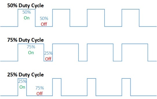
Now, let us see how to set a value for the CCPR1L which decides the duty cycle of a pulse. A duty cycle or power cycle is the fraction of one period in which a signal or system is active. The duty cycle is commonly expressed as a percentage or a ratio.
The PWM duty cycle is specified by writing to the CCPR1L register and to the CCP1CON<5:4> bits (Up to 10-bit resolution). The CCPR1L contains the eight MSbs and the CCP1CON<5:4> contains the two LSbs. This 10-bit value is represented by CCPR1L:CCP1CON<5:4>.
We know that a duty cycle is some % of the PR2 (period) register. We can calculate the value (CCPR1L: CCP1CON<5: 4>) and the value of PR2 using the below formula.
//Calculate the value of PR2 for the given PWM period

PWM Period = [(PR2) + 1] * 4 * TOSC * (TMR2 Prescale Value)


//Calculate the value of registers
//CCPR1L and CCP1CON<5:4> for the given duty cycle.

(CCPR1L:CCP1CON<5:4>) = PWM Duty Cycle / (TOSC * (TMR2 Prescale Value));
Where,
PWM frequency is defined as 1/[PWM period].
Oscillator frequency is defined as 1/TOSC.
For example, we use 20MHz clock and the o/p frequency is 5KHz;
whereas PWM period = 1/frequency (that will be 1/5000 = .0002)
.0005 = [PR2 + 1] • [1 / 20000000] • 16
PR2 + 1 = [.0002 • 20000000] / 16
PR2 + 1 = 250
PR2 = 249
PR2 = 0xF9 ( 249 in hex)
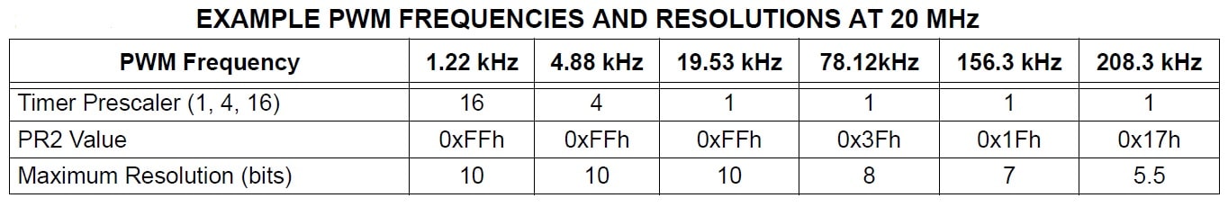
See the below table contains the value of PR2 register for given Fosc and Prescaler.
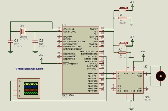
Pic microcontroller speed control project requirements:
- PIC16f877a
- L293d h-bridge Motor driver Ic
- DC Motor
- Crystal 20MHz
- Push Buttons
- connecting wires
- Breadboard or PCB
- Power Supply battery
You can check the Below book for a basic understanding of PIC Microcontroller and Embedded Systems: Using Assembly and C for PIC 18.
Check It:
C code to control DC Motor using the PIC Microcontroller using L293D:
Let’s see a C program for the PIC microcontroller where 2 switches controlling the speed of the DC motor. The oscillator frequency is 20 Mhz, PWM is 5.00kHz, Prescaler value is 4 and PR2 is 0xF9.
The below table explains how the switches controlling the duty cycle of the PWM.
| S1 | S2 | PWM (Duty Cycle) |
| LOW | LOW | 25% |
| LOW | HIGH | 50% |
| HIGH | LOW | 75% |
| HIGH | HIGH | 100% |
#define _XTAL_FREQ 20000000
#define TMR2PRESCALE 4
#include <xc.h>
#include<stdint.h>
// BEGIN CONFIG
#pragma config FOSC = HS // Oscillator Selection bits (HS oscillator)
#pragma config WDTE = OFF // Watchdog Timer Enable bit (WDT enabled)
#pragma config PWRTE = OFF // Power-up Timer Enable bit (PWRT disabled)
#pragma config BOREN = ON // Brown-out Reset Enable bit (BOR enabled)
#pragma config LVP = OFF // Low-Voltage (Single-Supply) In-Circuit Serial Programming Enable bit (RB3 is digital I/O, HV on MCLR must be used for programming)
#pragma config CPD = OFF // Data EEPROM Memory Code Protection bit (Data EEPROM code protection off)
#pragma config WRT = OFF // Flash Program Memory Write Enable bits (Write protection off; all program memory may be written to by EECON control)
#pragma config CP = OFF // Flash Program Memory Code Protection bit (Code protection off)
//END CONFIG
//Switch Debounce time in us
#define DEBOUNCE_TIME  240
//Switch Status
#define SWITCH_PRESSED    1
#define SWITCH_BOUNCE     0
//Define pins for motor
#define M_a    RD0
#define M_b    RD1
//Define pins for switch
#define S_1  RB0
#define S_2  RB1


// CCP1 module is used here to generate the required PWM
// Timer2 module is used to generate the PWM
// This PWM has 10bit resolution

//max Duty
uint32_t pwmMaxDuty(const uint32_t freq)
{
  return(_XTAL_FREQ/(freq*TMR2PRESCALE));
}

//Calculate the PR2 value
void initPwm(const uint32_t freq)
{
    //calculate period register value
    PR2 = (uint8_t)((_XTAL_FREQ/(freq*4*TMR2PRESCALE)) - 1);
}

//Give a value in between 0 and 1024 for duty-cycle
void applyPWMDutyCycle(uint16_t dutyCycle, const uint32_t freq)
{
    if(dutyCycle<1024)
    {
        //1023 because 10 bit resolution
        dutyCycle = (uint16_t)(((float)dutyCycle/1023)*pwmMaxDuty(freq));
        CCP1CON &= 0xCF;                 // Make bit4 and 5 zero (Store fraction part of duty cycle)
        CCP1CON |= (0x30&(dutyCycle<<4)); // Assign Last 2 LSBs to CCP1CON
        CCPR1L = (uint8_t)(dutyCycle>>2); // Put MSB 8 bits in CCPR1L
    }
}

//Init the Port pin
void initPort()
{
    TRISB0 = 1;  // Make S_1 pin an input
    TRISB1 = 1;  // Make S_2 pin an input
    TRISD0 = 0;  // Make M_a pin an output
    TRISD1 = 0;  // Make M_b pin an output
    TRISC2 = 0;   //Make pin output for PWM
}

//Run motor clockwise
void motorRunClockWise()
{
    M_a=1;
    M_b=0;
    M_a=1;
    M_b=0;
}

//configure and start PWM1
void startPwm()
{
    CCP1CON = 0x0C; // Configure CCP1 module in PWM mode
    T2CON = 0x01;  // Set Prescaler to be 4
    T2CON |= 0x04; // Enable the Timer2, hence enable the PWM.
}

//Function to check the status of Switch S1
int isS1Pressed()
{
    int switchStatus =  SWITCH_BOUNCE;
    if(S_1 == SWITCH_PRESSED)
    {
        //Wait time more then bouncing period
        __delay_us(DEBOUNCE_TIME);
        switchStatus =  S_1? SWITCH_PRESSED : SWITCH_BOUNCE;
    }
    return switchStatus ;
}

//Function to check the status of Switch S2
int isS2Pressed()
{
    int switchStatus =  SWITCH_BOUNCE;
    if(S_2 == SWITCH_PRESSED)
    {
        //Wait time more then bouncing period
        __delay_us(DEBOUNCE_TIME);
        switchStatus =  S_2? SWITCH_PRESSED : SWITCH_BOUNCE;
    }
    return switchStatus ;
}

//main function
void main()
{
    uint16_t dutycycle = 0;
    uint16_t dutyCycleApply = 0;
    const uint32_t pwmFreq = 5000;


    initPort(); //Init Gpio port
    motorRunClockWise(); //Run motor clockwise
    initPwm(pwmFreq); // Initialize PWM
    applyPWMDutyCycle(dutycycle,pwmFreq);
    startPwm();
    do
    {
        //Check the switch status for duty cycle
        dutycycle = (isS1Pressed() && isS2Pressed())? 1023: dutycycle; //100% duty cycle
        dutycycle = (isS1Pressed() && !isS2Pressed())? 768: dutycycle; //75% duty cycle
        dutycycle = (!isS1Pressed() && isS2Pressed())? 512: dutycycle; //50% duty cycle
        dutycycle = (!isS1Pressed() && !isS2Pressed())? 256: dutycycle;//25% duty cycle
        if (dutycycle != dutyCycleApply)
        {
            applyPWMDutyCycle(dutycycle,pwmFreq);
            dutyCycleApply = dutycycle;
        }
    }
    while(1);  //super loop
}
Video to explain the working of the mentioned C code,
Recommended Post:
- Interfacing DC motor with PIC Microcontroller using L293d
- LED Interfacing with PIC Microcontroller.
- Best gift for programmers.
- Best electronic kits for programmers.
- Read and Write to Internal EEPROM of PIC Microcontroller.
- Best mouse for programming and coding
- Interfacing EEPROM with PIC Microcontroller – I2C Based.
- Interfacing RTC DS1307 with PIC Microcontroller.
- Display Custom Characters on LCD using PIC Microcontroller.
- PIC microcontroller tutorials.
- Led Blinking program in c for 8051.
- 8051 Microcontroller Pin Diagram and Pin Description.
- 8051 Architecture.