
In the article, we see the interfacing EEPROM with PIC Microcontrollers using the I2C Protocol. In the real world, microcontrollers have a limited amount of memory. Sometimes the limited amount of memory becomes a big issue and creates a roadblock to the development of a project.
Each microcontroller provides flexibility to connect an external memory to store the required data. These data can store in memory by using the I2C, SPI or other communication protocol.
Here, I am explaining an example, where I will store a single byte in an EEPROM and after that, I will read back the written byte from the EEPROM. For verification, I will compare read bytes from the bytes which have been written and toggle LED if both the bytes are equal.
What is an EEPROM?
An EEPROM is a non-volatile memory that means it can store the data permanently without any power supply. EEPROM stands for Electrically Erasable Programmable Read-Only Memory. We can erase the EEPROM data by the UV eraser.
An EEPROM is slower than the flash memory. In flash memory, we can erase the whole sector at a time but in the case of EEPROM, we can erase a single byte at the time.
Some microcontrollers confine a small amount of EEPROM to store the extra bytes which are required in the program, for example, usernames and passwords.

There are many vendors who make different kinds of EEPROM but in this article, I will only discuss 24lc64 (manufactured by the microchip). The 24lc64 (EEPROM) is connected to the Microcontroller through the I2C bus protocol.
There some important features of 24lc64 (EEPROM)
- Organized as 8 blocks of 8kbit (64 Kbit).
- The interface through two-wire (I2C).
- Page write buffer up to 32 bytes
- We can read/ write on it approximately one million times.
- It can retain the data for more than 200 years.
Control bytes of 24lc64 (EEPROM)
Before starting the programming, we have to aware of the addressing of 24lc64 (EEPROM). It contains a control byte which sends by the master in I2C communication followed by a start condition. The control byte confines the control code, chip -select and read/write bits.
The control code for the 24lc64 is “1010” for the read and write operation. The chip select size is 3 bits (A2, A1, A0) it allows the user to connect the maximum of 8 devices to the I2c bus. The last bit of the control byte is read/write bits, this bit is zero for the write operation and one for the read operation.

Basic Requirements for interfacing EEPROM with PIC
Knowledge of I2C protocol
When you want to interface an EEPROM with a microcontroller then you need to have a good knowledge of I2C protocol. If you are not aware of the I2C protocol then don’t need to worry, it is a very simple serial communication protocol. So it’s my advice to you, before reading the remaining part of this article, read the I2C protocol.
Micro-controller
In our case, the Micro-controller works here as master and starts the communication to perform the read and write operation on EEPROM.
EEPROM memory
It’s storing device is used to store permanent data like user information (username, password). Here I am using the 24lc64 chip to store the data.
It has 8 blocks of 8kbit (8* 1024 bytes of data storage). The chip has storage location, each location has a unique address ranging from the (0 to 8191) and each location treat as a cell.
For example, after writing the data ‘K’ on the location 0x0001, if you read the location 0x0001 you will get ‘K’. Most important thing is to remember that each cell of 24lc64 can store 8 bits of the data(0 -255). So if you want to store the bigger data then you have to use more than one cell.
C Program to interfacing EEPROM with PIC microcontrollers:
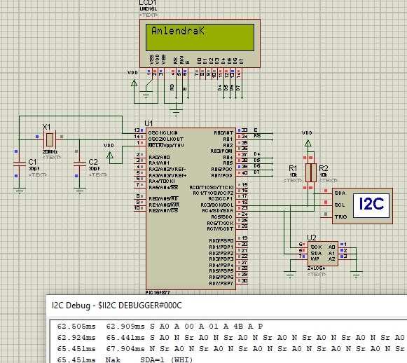
In this C program, we learn, how to write the byte in external EEPROM (24lc64) using I2C protocol and how to read the written byte from the EEPROM using I2C protocol. Here I am writing “Amlendrak” in external memory and reading it back and displaying on the 16×2 alphanumeric LCD.
/* Name     : main.c
*  Purpose  : Main file for internal EEPROM access code for PIC16F877.
*  Author   : Amlendra Kumar
*  Website  : https://aticleworld.com
*/
#include<htc.h>

// Configuration word for PIC16F877A
__CONFIG( FOSC_HS & WDTE_OFF & PWRTE_ON & CP_OFF & BOREN_ON
          & LVP_OFF & CPD_OFF & WRT_OFF & DEBUG_OFF);


// Define CPU Frequency
// This must be defined, if __delay_ms() or
// __delay_us() functions are used in the code
#define _XTAL_FREQ   20000000


// Define Pins for LCD
#define LCD_E    			RB0     // Enable pin for LCD
#define LCD_RS	 			RB1     // RS pin for LCD
#define LCD_Data_Bus_D4		RB4		// Data bus bit 4
#define LCD_Data_Bus_D5		RB5		// Data bus bit 5
#define LCD_Data_Bus_D6		RB6		// Data bus bit 6
#define LCD_Data_Bus_D7		RB7		// Data bus bit 7

// Define Pins direction register
#define LCD_E_Dir     			TRISB0
#define LCD_RS_Dir   	 		TRISB1
#define LCD_Data_Bus_Dir_D4   	TRISB4
#define LCD_Data_Bus_Dir_D5     TRISB5
#define LCD_Data_Bus_Dir_D6  	TRISB6
#define LCD_Data_Bus_Dir_D7 	TRISB7

// Constants
#define E_Delay       500


// Function Declarations
void WriteCommandToLCD(unsigned char);
void WriteDataToLCD(char);
void InitLCD(void);
void WriteStringToLCD(const char*);
void ClearLCDScreen(void);


// Define i2c pins
#define SDA			RC4				// Data pin for i2c
#define SCK			RC3				// Clock pin for i2c
#define SDA_DIR		TRISC4			// Data pin direction
#define SCK_DIR		TRISC3			// Clock pin direction

// Define i2c speed
#define I2C_SPEED	100				// kbps

//Function Declarations
void InitI2C(void);
void I2C_Start(void);
void I2C_ReStart(void);
void I2C_Stop(void);
void I2C_Send_ACK(void);
void I2C_Send_NACK(void);
bit  I2C_Write_Byte(unsigned char);
unsigned char I2C_Read_Byte(void);


// Define 24LC64 i2c device address
#define Device_Address_24LC64_EEPROM	0xA0


// Function Declarations
void Write_Byte_To_24LC64_EEPROM(unsigned int, unsigned char);
unsigned char Read_Byte_From_24LC64_EEPROM(unsigned int);
void Write_Page_To_24LC64_EEPROM(unsigned int, unsigned char*, unsigned char);
void Read_Bytes_From_24LC64_EEPROM(unsigned int, unsigned char*, unsigned int);


int main(void)
{
    unsigned char RxByte = 0;
    unsigned char TxArray[9] = "Amlendra";
    unsigned char RxArray[9] = { 0 };

    // Initialize LCD
    InitLCD();

    // Initialize i2c module
    InitI2C();

    // Write 'd' at 0x0001 address in EEPROM
    Write_Byte_To_24LC64_EEPROM(0x0001, 'K');
    // Read from 0x0001 address	from EEPROM
    RxByte = Read_Byte_From_24LC64_EEPROM(0x0001);

    // Write 9 bytes of TxArray starting from 0x0020 address in EEPROM
    Write_Page_To_24LC64_EEPROM(0x0020, TxArray, 9);
    // Read 9 bytes starting from 0x0020 address in EEPROM, save these bytes into RxArray
    Read_Bytes_From_24LC64_EEPROM(0x0020, RxArray, 9);

    // Display received char array on LCD display
    WriteStringToLCD(RxArray);

    // Display received char on LCD display
    WriteDataToLCD(RxByte);

    while(1)
    {
    }
    return 0;
}


//Function related to LCD

void ToggleEpinOfLCD(void)
{
    LCD_E = 1;                // Give a pulse on E pin
    __delay_us(E_Delay);      // so that LCD can latch the
    LCD_E = 0;                // data from data bus
    __delay_us(E_Delay);
}


void WriteCommandToLCD(unsigned char Command)
{
    LCD_RS = 0;				  // It is a command

    PORTB &= 0x0F;			  // Make Data pins zero
    PORTB |= (Command&0xF0);  // Write Upper nibble of data
    ToggleEpinOfLCD();		  // Give pulse on E pin

    PORTB &= 0x0F;			  // Make Data pins zero
    PORTB |= ((Command<<4)&0xF0); // Write Lower nibble of data
    ToggleEpinOfLCD();		  // Give pulse on E pin
}


void WriteDataToLCD(char LCDChar)
{
    LCD_RS = 1;				  // It is data

    PORTB &= 0x0F;			  // Make Data pins zero
    PORTB |= (LCDChar&0xF0);  // Write Upper nibble of data
    ToggleEpinOfLCD();		  // Give pulse on E pin

    PORTB &= 0x0F;			  // Make Data pins zero
    PORTB |= ((LCDChar<<4)&0xF0); // Write Lower nibble of data
    ToggleEpinOfLCD();		  // Give pulse on E pin
}


void InitLCD(void)
{
    // Firstly make all pins output
    LCD_E  		 		 = 0;   // E  = 0
    LCD_RS  	 		 = 0;   // RS = 0
    LCD_Data_Bus_D4		 = 0;  	// Data bus = 0
    LCD_Data_Bus_D5		 = 0;  	// Data bus = 0
    LCD_Data_Bus_D6		 = 0;  	// Data bus = 0
    LCD_Data_Bus_D7		 = 0;  	// Data bus = 0
    LCD_E_Dir    		 = 0;   // Make Output
    LCD_RS_Dir    	 	 = 0;   // Make Output
    LCD_Data_Bus_Dir_D4  = 0;   // Make Output
    LCD_Data_Bus_Dir_D5  = 0;   // Make Output
    LCD_Data_Bus_Dir_D6  = 0;   // Make Output
    LCD_Data_Bus_Dir_D7  = 0;   // Make Output

    ///////////////// Reset process from datasheet //////////////
    __delay_ms(40);

    PORTB &= 0x0F;			  // Make Data pins zero
    PORTB |= 0x30;			  // Write 0x3 value on data bus
    ToggleEpinOfLCD();		  // Give pulse on E pin

    __delay_ms(6);

    PORTB &= 0x0F;			  // Make Data pins zero
    PORTB |= 0x30;			  // Write 0x3 value on data bus
    ToggleEpinOfLCD();		  // Give pulse on E pin

    __delay_us(300);

    PORTB &= 0x0F;			  // Make Data pins zero
    PORTB |= 0x30;			  // Write 0x3 value on data bus
    ToggleEpinOfLCD();		  // Give pulse on E pin

    __delay_ms(2);

    PORTB &= 0x0F;			  // Make Data pins zero
    PORTB |= 0x20;			  // Write 0x2 value on data bus
    ToggleEpinOfLCD();		  // Give pulse on E pin

    __delay_ms(2);
    /////////////// Reset Process End ////////////////
    WriteCommandToLCD(0x28);    //function set
    WriteCommandToLCD(0x0c);    //display on,cursor off,blink off
    WriteCommandToLCD(0x01);    //clear display
    WriteCommandToLCD(0x06);    //entry mode, set increment
}


void WriteStringToLCD(const char *s)
{
    while(*s)
    {
        WriteDataToLCD(*s++);   // print first character on LCD
    }
}


void ClearLCDScreen(void)       // Clear the Screen and return cursor to zero position
{
    WriteCommandToLCD(0x01);    // Clear the screen
    __delay_ms(2);              // Delay for cursor to return at zero position
}


//Function related to I2C

// Function Purpose: Configure I2C module
void InitI2C(void)
{
    SDA_DIR = 1;		// Make SDA and
    SCK_DIR = 1;		// SCK pins input

    SSPADD  = ((_XTAL_FREQ/4000)/I2C_SPEED) - 1;
    SSPSTAT = 0x80;		// Slew Rate control is disabled
    SSPCON  = 0x28;		// Select and enable I2C in master mode
}


// Function Purpose: I2C_Start sends start bit sequence
void I2C_Start(void)
{
    SEN = 1;			// Send start bit
    while(!SSPIF);		// Wait for it to complete
    SSPIF = 0;			// Clear the flag bit
}


// Function Purpose: I2C_ReStart sends start bit sequence
void I2C_ReStart(void)
{
    RSEN = 1;			// Send Restart bit
    while(!SSPIF);		// Wait for it to complete
    SSPIF = 0;			// Clear the flag bit
}


//Function : I2C_Stop sends stop bit sequence
void I2C_Stop(void)
{
    PEN = 1;			// Send stop bit
    while(!SSPIF);		// Wait for it to complete
    SSPIF = 0;			// Clear the flag bit
}


//Function : I2C_Send_ACK sends ACK bit sequence
void I2C_Send_ACK(void)
{
    ACKDT = 0;			// 0 means ACK
    ACKEN = 1;			// Send ACKDT value
    while(!SSPIF);		// Wait for it to complete
    SSPIF = 0;			// Clear the flag bit
}


//Function : I2C_Send_NACK sends NACK bit sequence
void I2C_Send_NACK(void)
{
    ACKDT = 1;			// 1 means NACK
    ACKEN = 1;			// Send ACKDT value
    while(!SSPIF);		// Wait for it to complete
    SSPIF = 0;			// Clear the flag bit
}


// Function Purpose: I2C_Write_Byte transfers one byte
bit I2C_Write_Byte(unsigned char Byte)
{
    SSPBUF = Byte;		// Send Byte value
    while(!SSPIF);		// Wait for it to complete
    SSPIF = 0;			// Clear the flag bit

    return ACKSTAT;		// Return ACK/NACK from slave
}


// Function Purpose: I2C_Read_Byte reads one byte
unsigned char I2C_Read_Byte(void)
{
    RCEN = 1;			// Enable reception of 8 bits
    while(!SSPIF);		// Wait for it to complete
    SSPIF = 0;			// Clear the flag bit

    return SSPBUF;		// Return received byte
}


//Function related to eeprom

// Function Purpose: Write_Byte_To_24LC64_EEPROM writes a single byte on given address
// Address can have any value fromm 0 to 0x1FFF, and DataByte can have a value of 0 to 0xFF.
void Write_Byte_To_24LC64_EEPROM(unsigned int Address, unsigned char DataByte)
{
    I2C_Start();										// Start i2c communication

    // Send i2c address of 24LC64 with write command
    while(I2C_Write_Byte(Device_Address_24LC64_EEPROM + 0) == 1)// Wait until device is free
    {
        I2C_ReStart();
    }

    I2C_Write_Byte(Address>>8);							// Write Address upper byte
    I2C_Write_Byte((unsigned char)Address);				// Write Address lower byte
    I2C_Write_Byte(DataByte);							// Write data byte
    I2C_Stop();											// Stop i2c communication
}


// Function Purpose: Read_Byte_From_24LC64_EEPROM reads a single byte from given address
// Address can have any value fromm 0 to 0x1FFF.
unsigned char Read_Byte_From_24LC64_EEPROM(unsigned int Address)
{
    unsigned char Byte = 0;								// Variable to store Received byte

    I2C_Start();										// Start i2c communication

    // Send i2c address of 24LC64 with write command
    while(I2C_Write_Byte(Device_Address_24LC64_EEPROM + 0) == 1)// Wait until device is free
    {
        I2C_ReStart();
    }

    I2C_Write_Byte(Address>>8);							// Write Address upper byte
    I2C_Write_Byte((unsigned char)Address);				// Write Address lower byte
    I2C_ReStart();										// Restart i2c

    // Send i2c address of 24LC64 EEPROM with read command
    I2C_Write_Byte(Device_Address_24LC64_EEPROM + 1);

    Byte = I2C_Read_Byte();								// Read byte from EEPROM

    I2C_Send_NACK();									// Give NACK to stop reading
    I2C_Stop();											// Stop i2c communication

    return Byte;				// Return the byte received from 24LC64 EEPROM
}


// Function Purpose: Write_Page_To_24LC64_EEPROM writes a page on given address
// Address can have value 0, 32, 64, .... only and pData is pointer to the array
// containing NoOfBytes bytes in it. NoOfBytes can have a value from 1 to 32 only.
void Write_Page_To_24LC64_EEPROM(unsigned int Address,unsigned char* pData,unsigned char NoOfBytes)
{
    unsigned int i;

    I2C_Start();										// Start i2c communication

    // Send i2c address of 24LC64 with write command
    while(I2C_Write_Byte(Device_Address_24LC64_EEPROM + 0) == 1)// Wait until device is free
    {
        I2C_ReStart();
    }

    I2C_Write_Byte(Address>>8);							// Write Address upper byte
    I2C_Write_Byte((unsigned char)Address);				// Write Address lower byte

    for(i=0; i<NoOfBytes; i++)							// Write NoOfBytes
        I2C_Write_Byte(pData[i]);						// Write data byte

    I2C_Stop();											// Stop i2c communication
}


// Function Purpose: Read_Bytes_From_24LC64_EEPROM reads a NoOfBytes bytes from given starting address.
// Address can have any value fromm 0 to 0x1FFF. Also, NoOfBytes can have any value 0 to 0x1FFF.
// Read bytes are returned in pData array.
void Read_Bytes_From_24LC64_EEPROM(unsigned int Address, unsigned char* pData, unsigned int NoOfBytes)
{
    unsigned int i;

    I2C_Start();										// Start i2c communication

    // Send i2c address of 24LC64 with write command
    while(I2C_Write_Byte(Device_Address_24LC64_EEPROM + 0) == 1)// Wait until device is free
    {
        I2C_ReStart();
    }

    I2C_Write_Byte(Address>>8);							// Write Address upper byte
    I2C_Write_Byte((unsigned char)Address);				// Write Address lower byte
    I2C_ReStart();										// Restart i2c

    // Send i2c address of 24LC64 EEPROM with read command
    I2C_Write_Byte(Device_Address_24LC64_EEPROM + 1);

    pData[0] = I2C_Read_Byte();							// Read First byte from EEPROM

    for(i=1; i<NoOfBytes; i++)							// Read NoOfBytes
    {
        I2C_Send_ACK();					// Give Ack to slave to start receiving next byte
        pData[i] = I2C_Read_Byte();		// Read next byte from EEPROM
    }

    I2C_Send_NACK();									// Give NACK to stop reading
    I2C_Stop();											// Stop i2c communication
}
Proteus Simulation:
Recommended Post:
- Interfacing RTC DS1307 with PIC Microcontroller.
- Display Custom Characters on LCD using PIC Microcontroller.
- Led blinking program in c for 8051.
- Interfacing of switch and led using the 8051
- Interfacing of Relay with 8051 microcontroller
- Moving message display on LCD using 8051
- LCD 4-bit mode c code for 8051.
- Create LCD custom characters for 16×2 alphanumeric LCD
- Interfacing of keypad with 8051
- Electronic digital lock using the 8051
- Interfacing of EEPROM with 8051 microcontrollers using I2C
- Embedded c interview questions.
- 8051 Microcontroller Pin Diagram and Pin Description.
- Can protocol interview questions.
- 8051 Architecture.