
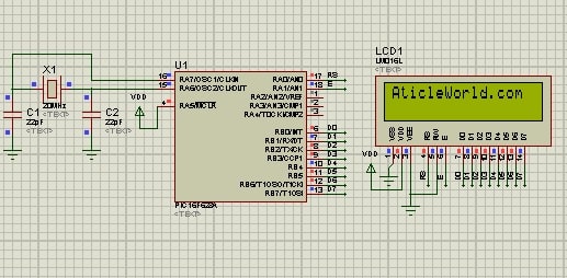
In this blog post, we will learn how to interface 16*2 Alphanumeric LCD with PIC Microcontroller (PIC16F877A) in an 8-bit Mode. We will also see the circuit diagram of LCD 8-bit interfacing with PIC Microcontroller.
Nowadays alphanumeric LCD is used in many devices to display the message, like printer, coffee machine, remote, etc. Alphanumeric LCD comes in different sizes 8*1, 8*2, 16*1, 16*2 or 20*4, etc and it displays only alphanumeric characters (have the ASCII value).
We can also display a custom character on LCD by generating custom characters. If you want to know more about it to how to display the custom character on LCD then you must see the below articles,
- Create LCD custom characters for 16×2 alphanumeric LCD.
- Display Custom Characters on LCD using PIC Microcontroller.
Pin Configuration of 16*2 Alphanumeric LCD:
A 16×2 Liquid Crystal Display has two rows and each row contains 16 columns. There are 16 pins in the LCD module, the pin configuration us given below,

| Ground pin | ||
| Power supply pin of 5V | ||
| Used for adjusting the contrast commonly attached to the potentiometer. | ||
| RS is the register select pin used to write display data to the LCD (characters), this pin has to be high when writing the data to the LCD. During the initializing sequence and other commands, this pin should low.
RS = 0; Select command resistor. RS = 1; Select data resistor. |
||
| Reading and writing data to the LCD for reading the data R/W pin should be high (R/W=1) to write the data to LCD R/W pin should be low (R/W=0).
R/W = 0; write operation. R/W = 1; Read operation. |
||
| Enable pin is for starting or enabling the module. A high to the low pulse of about 450ns pulse is given to this pin. | ||
| D0-D7 Data pins for giving data(normal data like numbers characters or command data) which is meant to be displayed | ||
| Back-light of the LCD which should be connected to Vcc | ||
| Back-light of LCD which should be connected to ground. |
Some useful commands for 16×2 Alphanumeric LCD:
Below I am mentioning few commands related to the 16×2 LCD. You can interface 16×2 LCD in two-mode 8bit and 4bit.
| For switching on LCD, blinking the cursor. | |
| Clearing the screen | |
| Return home. | |
| Decrement cursor | |
| Increment cursor | |
| Display on and also cursor on | |
| Force cursor to the beginning of the first line | |
| Force cursor to the beginning of the second line | |
| Use two lines and 5×7 matrix | |
| Cursor line 1 position 3 | |
| Activate the second line | |
| Jump to second-line position 3 | |
| Jump to the second line position1 |
Steps to send command on 16×2 LCD:
- E=1; enable pin should be high.
- RS=0; Register select should be low.
- R/W=0; Read/Write pin should be low.
Steps to send the character on 16×2 LCD:
- E=1; enable pin should be high.
- RS=1; Register select should be high.
- R/W=0; Read/Write pin should be low.
So let us see code that explains the LCD 8-bit interfacing with PIC Microcontroller and how to display characters on 16X2 LCD using PIC microcontroller.
In this blog post, I have written two codes one to display “Aticleworld.com” and second to display charging a “Hello world!”. I have used MPLAB v8.85 with the HI-TECH C v9.83 compiler to creating this project “16*2 Character LCD Interfacing with PIC Microcontroller in 8-bit Mode”.
1.) Display “Aticleworld.com” on 16×2 alphanumeric LCD:
/* Name     : main.c
*  Purpose  : Main file for using LCD with PIC16F628A in 8bit mode.
*  Author   : Amlendra Kumar
*  Website  : https://aticleworld.com
*/
#include<htc.h>

// Configuration word for PIC16F877A
__CONFIG( FOSC_HS & WDTE_OFF & PWRTE_ON & CP_OFF & BOREN_ON
          & LVP_OFF & CPD_OFF & WRT_OFF & DEBUG_OFF);


// Define CPU Frequency
// This must be defined, if __delay_ms() or
// __delay_us() functions are used in the code
#define _XTAL_FREQ   20000000


// Define Pins
#define LCD_E    		RA1   // Enable pin for LCD
#define LCD_RS	 		RA0   // RS pin for LCD
#define LCD_Data_Bus 	PORTB // Data bus for LCD

// Define Pins direction register
#define LCD_E_Dir     		TRISA1
#define LCD_RS_Dir   	 	TRISA0
#define LCD_Data_Bus_Dir 	TRISB

// Constants
#define E_Delay       500


// Function Declarations
void WriteCommandToLCD(unsigned char);
void WriteDataToLCD(char);
void InitLCD(void);
void WriteStringToLCD(const char*);
void ClearLCDScreen(void);


//Program start from here
int main(void)
{
    CMCON = 0x07;						// Turn comparator off
    InitLCD();						    // Initialize LCD in 8bit mode
    const char msg[] = "AticleWorld.com";

    ClearLCDScreen();					// Clear LCD screen
    WriteStringToLCD(msg);	// Write Hello World on LCD

    while(1)
    {
    }

    return 0;
}


void ToggleEpinOfLCD(void)
{
    LCD_E = 1;                // Give a pulse on E pin
    __delay_us(E_Delay);      // so that LCD can latch the
    LCD_E = 0;                // data from data bus
    __delay_us(E_Delay);
}


void WriteCommandToLCD(unsigned char Command)
{
    LCD_RS = 0;               // It is a command
    LCD_Data_Bus = Command;   // Write Command value on data bus

    ToggleEpinOfLCD();
}

void WriteDataToLCD(char LCDChar)
{
    LCD_RS = 1;               // It is data
    LCD_Data_Bus = LCDChar;   // Write Data value on data bus

    ToggleEpinOfLCD();
}

void InitLCD(void)
{
    // Firstly make all pins output
    LCD_E   	     = 0;      // E = 0
    LCD_RS    	     = 0;      // D = 0
    LCD_Data_Bus     = 0;      // CLK = 0
    LCD_E_Dir        = 0;      // Make Output
    LCD_RS_Dir       = 0;      // Make Output
    LCD_Data_Bus_Dir = 0;      // Make Output

    WriteCommandToLCD(0x38);    //function set
    WriteCommandToLCD(0x0c);    //display on,cursor off,blink off
    WriteCommandToLCD(0x01);    //clear display
    WriteCommandToLCD(0x06);    //entry mode, set increment
}

void WriteStringToLCD(const char *s)
{
    while(*s)
    {
        WriteDataToLCD(*s++);   // print first character on LCD
    }
}


void ClearLCDScreen(void)
{
    WriteCommandToLCD(0x01);    // Clear the screen
    __delay_ms(2);              // Delay for cursor to return at zero position
}
Proteus Simulation LCD 8-bit interfacing with PIC Microcontroller:
Code Analysis:
InitLCD():
This function is used to initialize the LCD with proper commands. Below I am mentioning some commands which are used in LCD initialization.
0x38 is used for 8-bit data initialization.
0x0C for making LCD display on and cursor off.
0X01 for clearing the display of the LCD.
0x80 for positioning the cursor at first line.
WriteCommandToLCD():
Whenever you send the command on 16×2 LCD, you have to set RS and RW pin low and E (enable) pin high. In code, I have written a function WriteCommandToLCD() which set RS pin low and E pin high. You can see the circuit I have already set RW pin low with the connection.
void WriteCommandToLCD(unsigned char Command)
{
    LCD_RS = 0;               // It is a command
    LCD_Data_Bus = Command;   // Write Command value on data bus
    ToggleEpinOfLCD();
}
WriteDataToLCD():
Whenever you send the character on 16×2 LCD for display, you have to set RS pin high, RW pin low and E (enable) pin high. In code, I have written a function WriteDataToLCD() which set RS pin high and E pin high. Due to the hardware connection, the RW PIN already low.
void WriteDataToLCD(char LCDChar)
{
    LCD_RS = 1;               // It is data
    LCD_Data_Bus = LCDChar;   // Write Data value on data bus
    ToggleEpinOfLCD();
}
2.) Display moving message “Hello World!” on 16×2 alphanumeric LCD:
/* Name     : main.c
*  Purpose  : Main file for using LCD with PIC16F628A in 8bit mode.
*  Author   : Amlendra Kumar
*  Website  : https://aticleworld.com
*/
#include<htc.h>
#include<string.h>

// Configuration word for PIC16F877A
__CONFIG( FOSC_HS & WDTE_OFF & PWRTE_ON & CP_OFF & BOREN_ON
          & LVP_OFF & CPD_OFF & WRT_OFF & DEBUG_OFF);


// Define CPU Frequency
// This must be defined, if __delay_ms() or
// __delay_us() functions are used in the code
#define _XTAL_FREQ   20000000


// Define Pins
#define LCD_E    		RA1   // Enable pin for LCD
#define LCD_RS	 		RA0   // RS pin for LCD
#define LCD_Data_Bus 	PORTB // Data bus for LCD

// Define Pins direction register
#define LCD_E_Dir     		TRISA1
#define LCD_RS_Dir   	 	TRISA0
#define LCD_Data_Bus_Dir 	TRISB

// Constants
#define E_Delay       500

// Function Declarations
void WriteCommandToLCD(unsigned char);
void WriteDataToLCD(char);
void InitLCD(void);
void WriteStringToLCD(const char*);
void ClearLCDScreen(void);


int main(void)
{
    CMCON = 0x07;// Turn comparator off
    InitLCD();	// Initialize LCD in 8bit mode
    int siLoop;
    int msgLen = 0;
    const char *msg ="Hello World!";

    msgLen = strlen(msg);
    while(1)
    {
        WriteCommandToLCD(0x8f); /*Address of DDRAM*/
        WriteStringToLCD(msg);	// Write Hello World on LCD
        for(siLoop=0; siLoop < msgLen; siLoop++)
        {
            WriteCommandToLCD(0x1c);
            __delay_us(100000);      // so that LCD can latch the
        }
    }
}


void ToggleEpinOfLCD(void)
{
    LCD_E = 1;                // Give a pulse on E pin
    __delay_us(E_Delay);      // so that LCD can latch the
    LCD_E = 0;                // data from data bus
    __delay_us(E_Delay);
}


void WriteCommandToLCD(unsigned char Command)
{
    LCD_RS = 0;               // It is a command
    LCD_Data_Bus = Command;   // Write Command value on data bus

    ToggleEpinOfLCD();
}

void WriteDataToLCD(char LCDChar)
{
    LCD_RS = 1;               // It is data
    LCD_Data_Bus = LCDChar;   // Write Data value on data bus

    ToggleEpinOfLCD();
}

void InitLCD(void)
{
    // Firstly make all pins output
    LCD_E   	     = 0;      // E = 0
    LCD_RS    	     = 0;      // D = 0
    LCD_Data_Bus     = 0;      // CLK = 0
    LCD_E_Dir        = 0;      // Make Output
    LCD_RS_Dir       = 0;      // Make Output
    LCD_Data_Bus_Dir = 0;      // Make Output


    WriteCommandToLCD(0x38);    //function set
    WriteCommandToLCD(0x0c);    //display on,cursor off,blink off
    WriteCommandToLCD(0x01);    //clear display
    WriteCommandToLCD(0x06);    //entry mode, set increment
}


void WriteStringToLCD(const char *s)
{
    while(*s)
    {
        WriteDataToLCD(*s++);   // print first character on LCD
    }
}


void ClearLCDScreen(void)
{
    WriteCommandToLCD(0x01);    // Clear the screen
    __delay_ms(2);              // Delay for cursor to return at zero position
}
Proteus Simulation LCD 8-bit interfacing with PIC Microcontroller:
Recommended Post:
- Push-button interfacing with PIC microcontroller.
- LED Interfacing with PIC Microcontroller.
- Read and Write to Internal EEPROM of PIC Microcontroller.
- Interfacing EEPROM with PIC Microcontroller – I2C Based.
- Interfacing RTC DS1307 with PIC Microcontroller.
- Display Custom Characters on LCD using PIC Microcontroller.
- Led blinking program in c for 8051.
- Interfacing of switch and led using the 8051
- Interfacing of Relay with 8051 microcontroller
- Moving message display on LCD using 8051
- LCD 4-bit mode c code for 8051.
- Create LCD custom characters for 16×2 alphanumeric LCD
- Interfacing of keypad with 8051
- Electronic digital lock using the 8051
- Interfacing of EEPROM with 8051 microcontrollers using I2C
- Embedded c interview questions.
- 8051 Microcontroller Pin Diagram and Pin Description.
- Can protocol interview questions.
- 8051 Architecture.