In this blog post, we will learn how to interface 16×2 Lcd with PIC Microcontroller (PIC16F877A). We will also learn how to display custom characters on 16X2 LCD using PIC microcontroller.
16X2 LCD has a controller HD44780, which provides the 8 locations (CGRAM ) to store the created LCD custom characters. We can use these custom characters as per our requirements. The custom characters are self-made characters which we design by our self.
In my previous blog post “How to create a custom character on 16×2 LCD”, I have described important registers and memory of HD44780. I have also explained how to interface alphanumeric LCD with 8051 microcontrollers, You can check this article to click the below link,
So let us see code that explains the interfacing of 16×2 LCD with PIC and how to display custom characters on 16X2 LCD using PIC microcontroller. In this blog post, I have written two codes one to display beetle and Arrow and second to display charging a battery. I have used MPLAB v8.85 with the HI-TECH C v9.83 compiler to creating this project “Display Custom Characters on LCD using PIC Microcontroller”.
1) Display beetle and Arrow on 16×2 alphanumeric LCD:
/* Name     : main.c
*  Purpose  : Main file for displaying custom characters on LCD with PIC16F628A.
*  Author   : Amlendra Kumar
*  Website  : https://aticleworld.com
*/
#include<htc.h>

// Configuration word for PIC16F877A
__CONFIG( FOSC_HS & WDTE_OFF & PWRTE_ON & CP_OFF & BOREN_ON
          & LVP_OFF & CPD_OFF & WRT_OFF & DEBUG_OFF);

// Define CPU Frequency
// This must be defined, if __delay_ms() or
// __delay_us() functions are used in the code
#define _XTAL_FREQ   20000000


// Define Pins for LCD
#define LCD_E    		RA1   // Enable pin for LCD
#define LCD_RS	 		RA0   // RS pin for LCD
#define LCD_Data_Bus 	PORTB // Data bus for LCD

// Define Pins direction registers
#define LCD_E_Dir     		TRISA1
#define LCD_RS_Dir   	 	TRISA0
#define LCD_Data_Bus_Dir 	TRISB

// -----------------------   Define Custom Characters ----------------------- //
/*Hex value to create the pattern (Arrow)*/
unsigned char ArrowObject[] = {0x00,0x04,0x08,0x1f,0x08,0x04,0x00,0x00};
/*Hex value to create the pattern (betel leaf)*/
unsigned char BetelObject[]= {0x00,0x1b,0x15,0x11,0x0a,0x04,0x00,0x00};
/*---------------------------------------------------*/

// Constants for delay
#define E_Delay       500


/*---------Start Function Declarations for LCD-------------*/
void WriteCommandToLCD(unsigned char);
void WriteDataToLCD(char);
void InitLCD(void);
void WriteStringToLCD(const char*);
void ClearLCDScreen(void);
void LCDBuildChar(unsigned char, unsigned char*);
/*---------------------End------------------------------*/


int main()
{
    CMCON = 0x07;			// Turn comparator off
    InitLCD();			    // Initialize LCD in 8bit mode

    WriteDataToLCD(0x00);   // Write Curvy Object on LCD
    WriteDataToLCD(' ');    // Space
    WriteDataToLCD(0x01);   // Write Square Box on LCD

    while(1)
    {
    }
    return 0;
}


void ToggleEpinOfLCD(void)
{
    LCD_E = 1;                // Give a pulse on E pin
    __delay_us(E_Delay);      // so that LCD can latch the
    LCD_E = 0;                // data from data bus
    __delay_us(E_Delay);
}


void WriteCommandToLCD(unsigned char Command)
{
    LCD_RS = 0;               // It is a command
    LCD_Data_Bus = Command;   // Write Command value on data bus
    ToggleEpinOfLCD();
}

void WriteDataToLCD(char LCDChar)
{
    LCD_RS = 1;               // It is data
    LCD_Data_Bus = LCDChar;   // Write Data value on data bus
    ToggleEpinOfLCD();
}

void InitLCD(void)
{
    // Firstly make all pins output
    LCD_E   	     = 0;      // E = 0
    LCD_RS    	     = 0;      // D = 0
    LCD_Data_Bus     = 0;      // CLK = 0
    LCD_E_Dir        = 0;      // Make Output
    LCD_RS_Dir       = 0;      // Make Output
    LCD_Data_Bus_Dir = 0;      // Make Output


    WriteCommandToLCD(0x38);    //function set
    WriteCommandToLCD(0x0c);    //display on,cursor off,blink off
    WriteCommandToLCD(0x01);    //clear display
    WriteCommandToLCD(0x06);    //entry mode, set increment

    /* ---------- Build Custom Characters -----------------*/
    LCDBuildChar(0, BetelObject); /* Build Character at position 0 */
    LCDBuildChar(1, ArrowObject);   /* Build Character at position 1 */
}


void WriteStringToLCD(const char *s)
{
    while(*s)
    {
        WriteDataToLCD(*s++);   // print first character on LCD
    }
}


void ClearLCDScreen(void)
{
    WriteCommandToLCD(0x01);    // Clear the screen
    __delay_ms(2);              // Delay for cursor to return at zero position
}


void LCDBuildChar(unsigned char loc, unsigned char *p)
{
    unsigned char i = 0;

    if(loc<8)                                 //If valid address
    {
        WriteCommandToLCD(0x40+(loc*8));      //Write to CGRAM
        for(i=0; i<8; i++)
        {
            WriteDataToLCD(p[i]);
        }             //Write the character pattern to CGRAM
    }
    WriteCommandToLCD(0x80);                  //shift back to DDRAM location 0
}
Proteus Simulation:
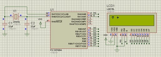
Code Analysis:
After seeing the code I hope that you will find the interfacing of LCD is easy with PIC. So let us decode each function which uses in LCD interfacing.
InitLCD():
It uses to initialize the LCD and create the custom character. I have used to array for beetle and arrow. The value of the array will change if you will change your custom design. There are many tools available to create a custom design. You can also create your custom design online, personally I found that the custom character generator tool is good to create a custom character.
/*Hex value to create the pattern (Arrow)*/
unsigned char ArrowObject[] = {0x00,0x04,0x08,0x1f,0x08,0x04,0x00,0x00};
/*Hex value to create the pattern (betel leaf)*/
unsigned char BetelObject[]= {0x00,0x1b,0x15,0x11,0x0a,0x04,0x00,0x00};
void InitLCD(void)
{
    // Firstly make all pins output
    LCD_E          = 0;      // E = 0
    LCD_RS           = 0;      // D = 0
    LCD_Data_Bus     = 0;      // CLK = 0
    LCD_E_Dir        = 0;      // Make Output
    LCD_RS_Dir       = 0;      // Make Output
    LCD_Data_Bus_Dir = 0;      // Make Output
    WriteCommandToLCD(0x38);    //function set
    WriteCommandToLCD(0x0c);    //display on,cursor off,blink off
    WriteCommandToLCD(0x01);    //clear display
    WriteCommandToLCD(0x06);    //entry mode, set increment
    /* ---------- Build Custom Characters -----------------*/
    LCDBuildChar(0, BetelObject); /* Build Character at position 0 */
    LCDBuildChar(1, ArrowObject);   /* Build Character at position 1 */
}
WriteCommandToLCD():
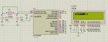
2) Display charging a battery on 16×2 alphanumeric LCD:
/* Name     : main.c
*  Purpose  : Main file for displaying custom characters on LCD with PIC16F628A.
*  Author   : Amlendra Kumar
*  Website  : https://aticleworld.com
*/
#include<htc.h>

// Configuration word for PIC16F877A
__CONFIG( FOSC_HS & WDTE_OFF & PWRTE_ON & CP_OFF & BOREN_ON
          & LVP_OFF & CPD_OFF & WRT_OFF & DEBUG_OFF);


// Define CPU Frequency
// This must be defined, if __delay_ms() or
// __delay_us() functions are used in the code
#define _XTAL_FREQ   20000000


// Define Pins
#define LCD_E    		RA1   // Enable pin for LCD
#define LCD_RS	 		RA0   // RS pin for LCD
#define LCD_Data_Bus 	PORTB // Data bus for LCD


// Define Pins direction registers
#define LCD_E_Dir     		TRISA1
#define LCD_RS_Dir   	 	TRISA0
#define LCD_Data_Bus_Dir 	TRISB


// ------- Define Custom Characters ----------- //

const unsigned char MyDesignObject[][8] =
{
    {0x00, 0x00, 0x0A, 0x1F, 0x1F, 0x0E, 0x04, 0x00},
    {0x0E, 0x1B, 0x11, 0x11, 0x11, 0x11, 0x1F, 0x00},
    {0x0E, 0x1B, 0x11, 0x11, 0x11, 0x1F, 0x1F, 0x00},
    {0x0E, 0x1B, 0x11, 0x11, 0x1F, 0x1F, 0x1F, 0x00},
    {0x0E, 0x1B, 0x11, 0x1F, 0x1F, 0x1F, 0x1F, 0x00},
    {0x0E, 0x1F, 0x1F, 0x1F, 0x1F, 0x1F, 0x1F, 0x00},
    {0x00, 0x04, 0x02, 0x1F, 0x02, 0x04, 0x00, 0x00},
    {0x00, 0x00, 0x0E, 0x11, 0x11, 0x0A, 0x1B, 0x00}
};
/*---------------------------------------------------*/

// Constants for delay
#define E_Delay       500

/*---------Start Function Declarations for LCD-------------*/
void WriteCommandToLCD(unsigned char);
void WriteDataToLCD(char);
void InitLCD(void);
void WriteStringToLCD(const char*);
void ClearLCDScreen(void);
void LCDBuildChar(unsigned char, unsigned char*);
/*---------------------End------------------------------*/


int main()
{
    unsigned char index = 0;
    CMCON = 0x07;	// Turn comparator off
    InitLCD();		// Initialize LCD in 8bit mode

    for(index =0; index < sizeof(MyDesignObject)/sizeof(MyDesignObject[0]); ++index)
    {
        WriteDataToLCD(index); /* Build Character at position index*/
    }
    while(1)
    {
    }

    return 0;
}

void ToggleEpinOfLCD(void)
{
    LCD_E = 1;                // Give a pulse on E pin
    __delay_us(E_Delay);      // so that LCD can latch the
    LCD_E = 0;                // data from data bus
    __delay_us(E_Delay);
}

void WriteCommandToLCD(unsigned char Command)
{
    LCD_RS = 0;               // It is a command
    LCD_Data_Bus = Command;   // Write Command value on data bus
    ToggleEpinOfLCD();
}

void WriteDataToLCD(char LCDChar)
{
    LCD_RS = 1;               // It is data
    LCD_Data_Bus = LCDChar;   // Write Data value on data bus
    ToggleEpinOfLCD();
}

void InitLCD(void)
{
    unsigned char index =0;
    // Firstly make all pins output
    LCD_E   	     = 0;      // E = 0
    LCD_RS    	     = 0;      // D = 0
    LCD_Data_Bus     = 0;      // CLK = 0
    LCD_E_Dir        = 0;      // Make Output
    LCD_RS_Dir       = 0;      // Make Output
    LCD_Data_Bus_Dir = 0;      // Make Output

    ///////////////// Reset process from data sheet //////////////
    __delay_ms(40);
    WriteCommandToLCD(0x30);

    __delay_ms(6);
    WriteCommandToLCD(0x30);

    __delay_us(300);
    WriteCommandToLCD(0x30);

    __delay_ms(2);
    /////////////////////////////////////////////////////

    WriteCommandToLCD(0x38);    //function set
    WriteCommandToLCD(0x0c);    //display on,cursor off,blink off
    WriteCommandToLCD(0x01);    //clear display
    WriteCommandToLCD(0x06);    //entry mode, set increment

    /* ---------- Build Custom Characters -----------------*/
    for(index =0; index < 8; ++index)
    {
        LCDBuildChar(index, MyDesignObject[index]); /* Build Character at position index*/
    }
}

void WriteStringToLCD(const char *s)
{
    while(*s)
    {
        WriteDataToLCD(*s++);   // print first character on LCD
    }
}

void ClearLCDScreen(void)
{
    WriteCommandToLCD(0x01);    // Clear the screen
    __delay_ms(2);              // Delay for cursor to return at zero position
}

void LCDBuildChar(unsigned char loc, unsigned char *p)
{
    unsigned char i = 0;
    if(loc<8)                                 //If valid address
    {
        WriteCommandToLCD(0x40+(loc*8));      //Write to CGRAM
        for(i=0; i<8; i++)
        {
            WriteDataToLCD(p[i]);
        }             //Write the character pattern to CGRAM
    }
    WriteCommandToLCD(0x80);                  //shift back to DDRAM location 0
}
Proteus Simulation:
Recommended Post:
- Led blinking program in c for 8051.
- Interfacing of switch and led using the 8051
- Interfacing of Relay with 8051 microcontroller
- Moving message display on LCD using 8051
- LCD 4-bit mode c code for 8051.
- Create LCD custom characters for 16×2 alphanumeric LCD
- Interfacing of keypad with 8051
- Electronic digital lock using the 8051
- Interfacing of EEPROM with 8051 microcontrollers using I2C
- Embedded c interview questions.
- 8051 Microcontroller Pin Diagram and Pin Description.
- Can protocol interview questions.
- 8051 Architecture.