
In the article, we will see how to read and write the internal EEPROM of PIC Microcontrollers. Generally, PIC microcontrollers come with some built-in EEPROM which is used to store data permanently.
An EEPROM is a non-volatile memory that means it can store the data permanently without any power supply. EEPROM stands for Electrically Erasable Programmable Read-Only Memory. We can erase the EEPROM data by the UV eraser.
The FLASH memory is faster than EEPROM. In flash memory, we have to erase the whole sector at a time but in the case of EEPROM, we can erase a single byte at the time.
A good example to use EEPROM is a digital lock system. In the digital lock, we can store access code in the EEPROM of the microcontroller. The access code will remain intact even after the power supply has been removed.
In my one project, I have used EEPROM to upgrade the firmware of my device over the Air. In today’s experiment, we will learn how to perform the basic Read and Write operations to the internal EEPROM of PIC16F877.
PIC16F877 microcontroller has 256 bytes of built-in EEPROM data space with an address range of 0x00 to 0xFF. I have used MPLAB v8.85 with the HI-TECH C v9.83 compiler to creating this project “Read and Write to Internal EEPROM of PIC Microcontroller”.
Here I assumed that you know how to blink an LED with PIC16F877 microcontroller. If you don’t then please read the below-mentioned Article,
- How to Blink Led Using PIC microcontroller.
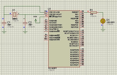
In the below code, I am using RB0 to interface an LED. The LED indicates a byte was successfully written in the internal EEPROM or not. If a byte is written successfully in EEPROM than LED will glow either it will off.
/* Name     : main.c
*  Purpose  : Main file for internal EEPROM access code for PIC16F877.
*  Author   : Amlendra Kumar
*  Website  : https://aticleworld.com
*/
#include<htc.h>

// Configuration word for PIC16F877A
__CONFIG( FOSC_HS & WDTE_OFF & PWRTE_ON & CP_OFF & BOREN_ON
          & LVP_OFF & CPD_OFF & WRT_OFF & DEBUG_OFF);

// Define CPU Frequency
// This must be defined, if __delay_ms() or
// __delay_us() functions are used in the code
#define _XTAL_FREQ   20000000
// Define Pins for LED
#define LED  RB0

int main(void)
{
    TRISB0 = 0;	 // Make RB0 pin output
    LED    = 0;  // Make RB0 low

    eeprom_write(0, 0x01); // Write 0x01 at 0 address location

    if( eeprom_read(0) == 0x01 )// Read from 0 address location
        LED = 1;// If eeprom was written correctly
    else
        LED = 0;// If eeprom was not written correctly

    while(1)
    {
    }
    return 0;
}
Proteus Simulation:
Recommended Post:
- Interfacing EEPROM with PIC Microcontroller – I2C Based.
- Interfacing RTC DS1307 with PIC Microcontroller.
- Display Custom Characters on LCD using PIC Microcontroller.
- Led blinking program in c for 8051.
- Interfacing of switch and led using the 8051
- Interfacing of Relay with 8051 microcontroller
- Moving message display on LCD using 8051
- LCD 4-bit mode c code for 8051.
- Create LCD custom characters for 16×2 alphanumeric LCD
- Interfacing of keypad with 8051
- Electronic digital lock using the 8051
- Interfacing of EEPROM with 8051 microcontrollers using I2C
- Embedded c interview questions.
- 8051 Microcontroller Pin Diagram and Pin Description.
- Can protocol interview questions.
- 8051 Architecture.