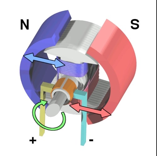
A DC motor is a type of electrical motors that converts direct current electrical energy into mechanical energy. Nowadays DC motor is used in many places from small toys to big industrial projects.
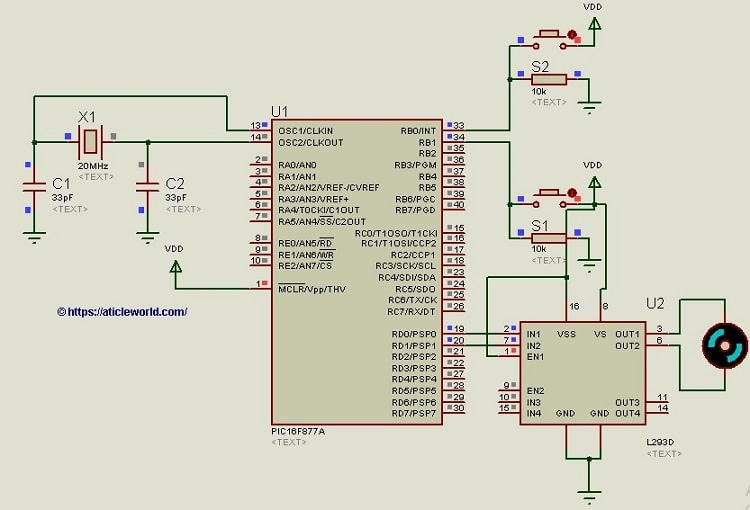
In this blog post, I will not much discuss the working concept of the DC motor. Here I will only discuss that how we can interface DC motor with PIC Microcontroller using L293D (motor driving IC).
If you have worked on the PIC Microcontroller, then you know that PIC Microcontrollers I/O PINs do not provide sufficient current and voltage. PIC Microcontrollers (16 series) usually operate at +5.5 or +2V supply and its I/O pin can provide only up to 25mA current.
This amount of voltage and current is not sufficient to drive the DC motor because commonly used DC Motors requires 12V supply and 300mA current. Also, DC Motors generate back EMF which is also harmful to PIC Microcontroller and can destroy your PIC microcontroller.
So to solve this problem we generally interface dc motor with pic microcontroller using the L293d a motor driving IC. So before writing the code let’s see some introduction of the L293d which helps to understand the interfacing of DC motor with PIC microcontroller and L293d.
L293d (Motor Driver IC):
It is a motor driver IC which used to control the DC motors. Motor driver IC is used as an interface between the PIC Microcontroller and DC motor. The most commonly used motor driver IC’s are from the L293 series such as L293D, L293NE, etc.
The L293 is designed to provide bidirectional drive currents of up to 1 A at voltages from 4.5 V to 36 V. L293d consists of two H-bridge, so it can control 2 DC motors simultaneously. H-bridge is the simplest circuit for controlling a low current rated motor.
Features of L293d:
- Wide Supply-Voltage Range: 4.5 V to 36 V.
- Separate Input-Logic Supply.
- Internal ESD Protection.
- Thermal Shutdown.
- High-Noise-Immunity Inputs.
- Output Current 600 mA Per Channel.
- Peak Output Current 1.2 A Per Channel
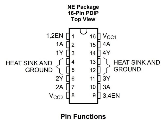
| Pin | Name | Function |
|---|---|---|
| 1 | Enable1,2 | Enable pin to control 1,2 driver |
| 2 | Input 1A | Input to control 1Y |
| 3 | Output 1Y | Output, connect to the motor |
| 4 | GND | Ground and heat sink |
| 5 | GND | Ground and heat sink |
| 6 | Output 2Y | Output, connect to the motor |
| 7 | Input 2A | Input to control 2Y |
| 8 | Vcc2 | Output supply voltage |
| 9 | Enable3,4 | Enable pin to control 3,4 driver |
| 10 | Input 3A | Input to control 3Y |
| 11 | Output 3Y | Output, connect to the motor |
| 12 | GND | Ground and heat sink |
| 13 | GND | Ground and heat sink |
| 14 | Output 4Y | Output, connect to the motor |
| 15 | Input 4A | Input to control 4Y |
| 16 | Vcc1 | Supply voltage(7 max) |
Note: 4 ground available in IC to reduces the heat and back EMF effect.
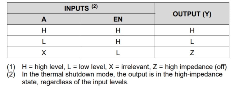
Function table of L293d:
DC Motor Interfacing with PIC Microcontroller using L293d:
Here we are going to create a small project where the motor and direction of the motor are controlled by two switch S1 and S2. Motor behavior depends on the switch status. In the below table I have described the motor status on the basis of switches S1 and S2.
| S1 | S2 | Motor Status |
| LOW | LOW | Stops |
| LOW | HIGH | Clockwise |
| HIGH | LOW | Anti-Clockwise |
| HIGH | HIGH | Stops |
You can check the Below book for a basic understanding of PIC Microcontroller and Embedded Systems: Using Assembly and C for PIC 18.
Check It:
C code for DC Motor Interfacing with PIC Microcontroller using L293D:
/* Name     : main.c
*  Purpose  : Interfacing DC Motor with PIC16F628A using L293D with .
*  Author   : Amlendra Kumar
*  Website  : https://aticleworld.com
*/
#include<htc.h>
// Configuration word for PIC16F877A
__CONFIG( FOSC_HS & WDTE_OFF & PWRTE_ON & CP_OFF & BOREN_ON
          & LVP_OFF & CPD_OFF & WRT_OFF & DEBUG_OFF);
// Define CPU Frequency
// This must be defined, if __delay_ms() or
// __delay_us() functions are used in the code
#define _XTAL_FREQ   20000000
//Switch Debounce time in us
#define DEBOUNCE_TIME  240
//Switch Status
#define SWITCH_PRESSED    1
#define SWITCH_BOUNCE     0
// Define pins for motor
#define M_a    RD0
#define M_b    RD1
// Define pins for switch
#define S_1  RB0
#define S_2  RB1


//Function to check the status of Switch S1
int isS1Pressed()
{
    int switchStatus =  SWITCH_BOUNCE;
    if(S_1 == SWITCH_PRESSED)
    {
        //Wait time more then bouncing period
        __delay_us(DEBOUNCE_TIME);
        switchStatus =  S_1? SWITCH_PRESSED : SWITCH_BOUNCE;
    }
    return switchStatus ;
}

//Function to check the status of Switch S2
int isS2Pressed()
{
    int switchStatus =  SWITCH_BOUNCE;
    if(S_2 == SWITCH_PRESSED)
    {
        //Wait time more then bouncing period
        __delay_us(DEBOUNCE_TIME);
        switchStatus =  S_2? SWITCH_PRESSED : SWITCH_BOUNCE;
    }
    return switchStatus ;
}

//Run motor clockwise
void motorRunClockWise()
{
    M_a=1;
    M_b=0;
    M_a=1;
    M_b=0;
}

//Run motor Anti clockwise
void motorRunAntiClockWise()
{
    M_a=0;
    M_b=1;
    M_a=0;
    M_b=1;
}

//Stop the motor
void motorStop()
{
    M_a=0;
    M_b=0;
    M_a=0;
    M_b=0;
}

//init the motor
void motorInit()
{
    M_a=0;
    M_b=0;
    M_a=0;
    M_b=0;
}

//Program start from here
int main()
{
    TRISB0 = 1;  // Make S_1 pin an input
    TRISB1 = 1;  // Make S_2 pin an input
    TRISD0 = 0;  // Make M_a pin an output
    TRISD1 = 0;  // Make M_b pin an output
    motorInit(); //Init Motor
    //Super loop to continuously monitor the status of the switch
    while(1)
    {
        //Check the switch status
        if(isS1Pressed() && isS2Pressed())
        {
            motorStop();
        }
        else if(isS1Pressed() && !isS2Pressed())
        {
            motorRunClockWise();
        }
        else if(!isS1Pressed() && isS2Pressed())
        {
            motorRunAntiClockWise();
        }
        else if(!isS1Pressed() && !isS2Pressed())
        {
            motorStop();
        }
    }
    return 0;
}
Recommended Post:
- Control DC Motor using the PIC Microcontroller and PWM.
- LED Interfacing with PIC Microcontroller.
- Best gift for programmers.
- Best electronic kits for programmers.
- Read and Write to Internal EEPROM of PIC Microcontroller.
- Best mouse for programming and coding
- Interfacing EEPROM with PIC Microcontroller – I2C Based.
- Interfacing RTC DS1307 with PIC Microcontroller.
- Display Custom Characters on LCD using PIC Microcontroller.
- PIC microcontroller tutorials.
- Led Blinking program in c for 8051.
- 8051 Microcontroller Pin Diagram and Pin Description.
- 8051 Architecture.
