This project shows how to use the STONE display, STM32 microcontroller, ultrasonic sensors, and a servo. The purpose of the project is to be able to display the distance measured by ultrasound in real-time through the STONE display.
Supplies used in the project:
The display uses an 8-inch STONE screen, 8-inch intelligent TFT-LCD (thin-film transistor – liquid crystal display) industrial display module 8-inch intelligent TFT-LCD (thin-film transistor – liquid crystal display) industrial display module
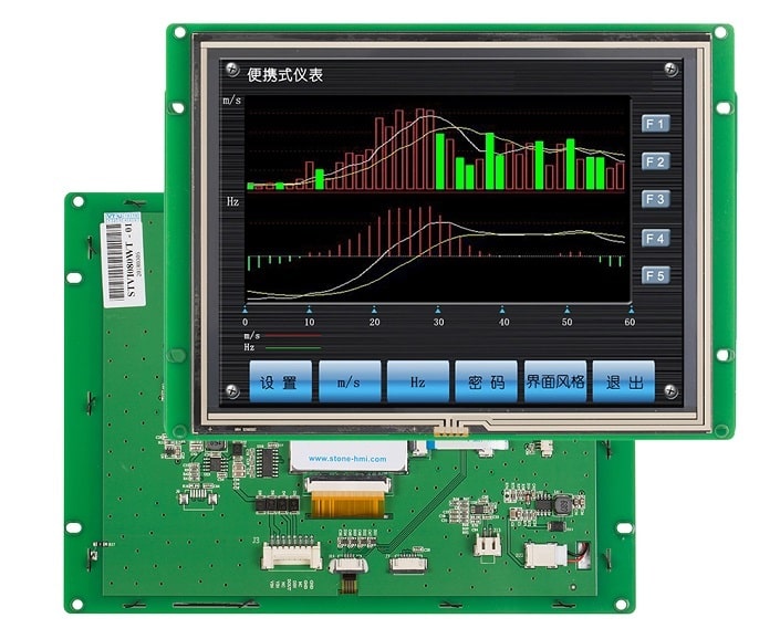
The intelligent TFT LCD module with Cortex-M4 32-bit CPU can be controlled by Any MCU through simple Hex commands via the UART port.
STONE provides TOOLBOX software for engineers to easily and visually set up various functions on the GUI, such as text, numbers, curves, image switching, keyboard, progress bar, slider, dial, clock and touch buttons, data storage, USB download, video & audio.
Engineers can easily adopt TFT-LCD color user interface and touch functions on various industrial devices and also reduce a lot of development time and cost.
Easy to use:
1. Design a set of beautiful “graphical user interface” and use our toolbox software to set various application functions on the GUI.
2. Connect directly to customer MCU via RS232, RS485, or TTL level, plug, and play.
3. Write the MCU program to control the TFT LCD module with 4 simple Hex commands.
For example,
If you want to display an image, you need to send the Image switch command. Like to display image-01 sending command, “0xA5 0x5A 0x04 0x80 0x03 0x00 0x01”. We can decode this command like,
0xA50x5A: frame header of each instruction 0x04: data length 0x80: write register instruction 0x03: Image switch instruction 0x000x01: Image_ID, the serial number of the image storage location
Application areas:
medical and beauty equipment, engineering machinery and vehicle equipment, electronic instruments, industrial control systems, electric power industry, civil electronic equipment, automation equipment, transportation equipment, etc.
Product parameters:
| Physical Parameter | |
| Model | STVI080WT-01 |
| Size (Inch) | 8 inch |
| Resolution | 800×RGB×600 |
| Color | 65536 colors (16 bit) |
| Viewing Area | 162mm×121.5mm |
| Pixel Spacing | 0.1905mm×0.0635mm (H×V) |
| Overall Dimension | 203mm×148.8mm×15.8mm(N)/17.4mm(T) |
| Net Weight | 435g(N)/550g(T) |
| TFT Panel | A Class Industry Panel |
| Touch Screen | Industry Level 4 wire resistance
Or without a touch screen is optional. |
| Backlight Parameter | |
| Backlight Type | LED |
| Brightness | 400 cd/m2(Brightness can be adjustable in 100 levels.) |
| Contrast | 500:1 |
| Backlight life | 30,000 hours |
| Viewing Angle | 70°/ 70°/ 50°/ 70°(L/R/U/D) |
| Working Temperature | -20°C ~ +70°C |
| Working Humidity | 55°C, 85% |
| Storage Temperature | -30°C ~ +80°C |
| Screen Mode | Digital |
| Performance Parameter | |
| CPU | CortexM4 |
| LCD Controller | CPLD EPM240 |
| Refresh Rate | 200MHz |
| Picture Switching Speed | 47 ms/frame (21 images/s) |
| Flash Memory | Standard 128MB, Extension 1GB |
| Memory Amount for picture | According to the capability of the image, Suggest “JPG” format. |
| Interface | RS232/ USB Interface |
| Image downloading | USB2.0 (12Mbps) & U storage Disk downloading |
| Voltage Range | DC6.0V ~ 35V (typical value: 12V) |
| Power | 2.8 W |
| Test Report | |
| MTBF | 4,250,000H |
| Working Temperature | -20°C ~ +70°C |
| Air Humidity | 60°C, 90% |
| Continuous Vibration Testing | 10-55Hz, 1.5mm, 10G |
| Impact Acceleration Testing | 6ms, 100G |
| ESD Testing | 10KV |
| Radiation Reliability Testing | 44W |
Product Advantages
1. Touch terminal, thin-film transistor-LCD display system
2. Any microcontroller can be controlled by a simple instruction set
3. Cost-effective HMI (Human Machine Touch Terminal)
Operation steps
1. Design a set of custom user interfaces.
2. Connect the device to the TFT-LCD module through RS232/RS485/TTL serial port.
3. Write a control program in any microcontroller with an instruction set (included in the product) to control the TFT-LCD module.
Auxiliary Software
We provide three software programs to assist in the operation of the TFT-LCD module.
1. Assistant software: for uploading pictures, files and demonstrating the instruction set.
2. Touch Control software: for generating touch control files.
3. Font software: for generating font files.
Working Principle
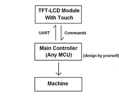
Through the existing command set provided by the product, this TFT-LCD module can generate command transmission and recognition with the main controller. The main controller receives the commands from the TFT-LCD module to operate the industrial equipment.
Note: The engineer can use any microcontroller to design the main controller.
All models
| Size (inches) | Resolution |
| 3.5’’ | 320*240; 320*480 |
| 4.3’’ | 480*272 |
| 5’’ | 640*480; 480*272; 800*480 |
| 5.6” | 640*480 |
| 7’’ | 800*480; 1024*600 |
| 8” | 800*600; 1024*768 |
| 9.7” | 1024*768 |
| 10.1” | 1024*600 |
| 10.4” | 800*600 |
| 12.1” | 1024*768 |
| 15.1” | 1024*768 |
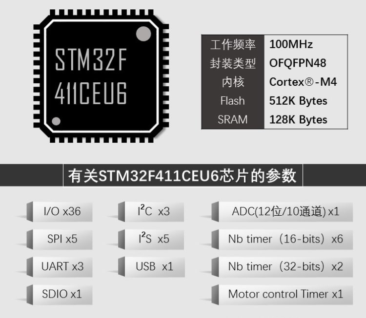
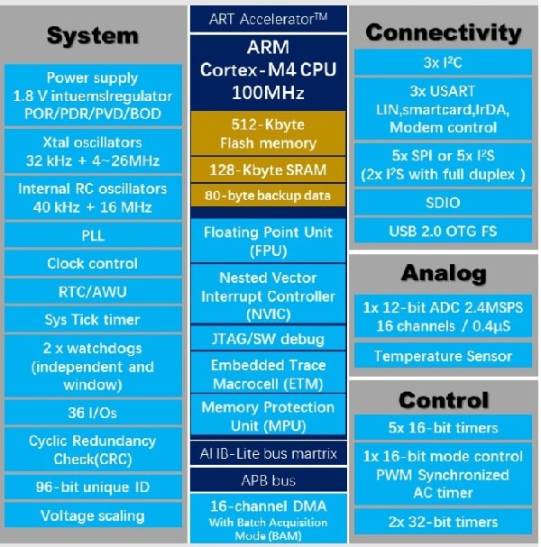
STM32F411 Micro-controller core board
Servo
Ultrasonic sensors:
Ultrasonic principle analysis
Ultrasonic (waves):
The human ear can hear the frequency of sound waves for 20HZ ~ 20KHz. when the vibration frequency of sound waves is greater than 20KHz or less than 20Hz, we can not hear the sound waves.
Therefore, we put the frequency higher than 20KHz sound waves called “ultrasonic”. Because of its good directionality, strong penetrating ability, easy to get more concentrated sound energy, in the water to spread far, can be used for measuring distance, measuring speed, cleaning, welding, stone crushing, sterilization, etc.
There are many applications in medicine, military, industry, and agriculture. Such as ultrasonic cleaning machine, ultrasonic humidifier, medical examination B ultrasound, color ultrasound, ultrasonic flaw detector, etc. Sound is generated by vibration, the device that can produce ultrasonic waves is the ultrasonic transducer, customarily called ultrasonic transducer, or ultrasonic probe.
The ultrasonic probe is mainly composed of a piezoelectric chip, which can both emit and receive ultrasonic waves. There can be many different materials that make up the chip. The size of the chip, such as the diameter and thickness also varies, so the performance of each probe is different, and its performance must be understood in advance before using it.
Commonly used is the piezoelectric ultrasonic generator, which works by using the resonance of a piezoelectric crystal. Inside the ultrasonic sensor, probes are two piezoelectric chips and a resonant plate.
When its two poles applied a pulse signal, its frequency is equal to the inherent oscillation frequency of the piezoelectric chip, the piezoelectric chip will resonate, and drive the resonance plate vibration, it will produce ultrasonic waves. Conversely, if the voltage is not applied between the two electrodes when the resonance plate receives ultrasonic waves, the piezoelectric chip will vibrate, converting mechanical energy into electrical signals, and then it becomes an ultrasonic receiver.
Ultrasonic sensor uses the principle of the piezoelectric effect to convert electrical energy and ultrasound into each other, that is, in the emission of ultrasound, the electrical energy will be converted into ultrasound emission; and in the reception, the ultrasonic vibration will be converted into an electrical signal.
Ultrasonic distance measurement principle:
The most commonly used method of ultrasonic distance measurement is the echo detection method, as follows, the ultrasonic transmitter launch ultrasound to a certain direction, at the moment of launch while the counter began timing, ultrasound propagation in the air, the way to encounter the obstacle surface blocking immediately reflected back, the ultrasonic receiver received back the reflected ultrasound immediately stop timing. Ultrasonic waves in the air propagation speed of 340m/s, according to the time recorded by the timer t, you can calculate the launch point from the obstacle surface distance s, that is: s = 340t/2
Ultrasonic emission circuit: by the 555 timer to generate 40KHZ pulse signal, added to the pins of the ultrasonic probe so that the internal resonance of the piezoelectric chip can be generated to emit ultrasonic waves outward.
Ultrasonic receiving circuit: As the electrical signal generated by the ultrasonic receiving probe is very weak, it needs to be amplified and processed. In the figure below, the transistor and operational amplifier LM324 constitute the amplifier circuit, which amplifies the received signal and then drives the relay.
Generally, use an integrated signal amplifier chip to amplify the signal. CX20106 is a special integrated preamplifier from SONY, which consists of a preamplifier, limiting amplifier, band-pass filter, detector, integrator, and rectifier circuit.
One of the preamplifiers has an automatic gain control function, which can ensure that when the ultrasonic sensor receives weak voltage which outputs from the reflected signal in the long-distance, the amplifier has a high gain when the input signal is strong in the near distance, the amplifier will not be overloaded.
The ultrasonic wave is also a kind of sound wave, its sound speed V is related to the temperature. When used, if the temperature of the propagation medium does not change much, the ultrasonic velocity can be approximated as being essentially constant during the propagation process.
If the distance measurement accuracy requirements are very high, the measurement results should be numerically corrected by the method of temperature compensation. v = 331.4 + 0.607T, where T is the actual temperature in ℃, v is the speed of ultrasound propagation in the medium in m/s, the actual measurement will generate several special cases, and lead to wrong measurement results due to the different angles of the sensor and the measured object, and the surface of the measured object may not be flat, as follows, it can be solved by rotating the probe angle several times to measure.
The main performance indicators of ultrasonic sensors include:
1. operating frequency: Operating frequency is the resonant frequency of the piezoelectric chip. When the frequency of the AC voltage added to both ends of it and the resonant frequency of the chip is equal, the output energy is the largest and the sensitivity is the highest.
2. Operating temperature: Because the Curie point of piezoelectric materials is generally high, especially with ultrasonic probe diagnosis, using less power, so the operating temperature is relatively low, it can work for a long time without failure. The temperature of medical ultrasound probes is relatively high and requires separate cooling equipment.
3. Sensitivity: It mainly depends on the manufacturing chip itself. The electromechanical coupling coefficient is large and the sensitivity is high.
Ultrasonic distance measurement module:
There are many good measurement modules on the market, with different price performance.
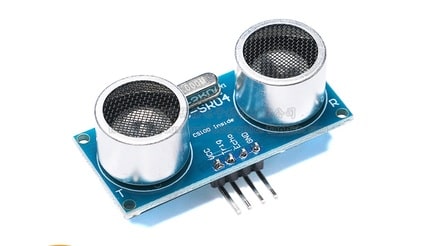
HC-SR04 ultrasonic distance measurement module can provide 2cm-400cm non-contact distance sensing function, the accuracy of distance measurement up to 3mm; the module includes ultrasonic transmitter, receiver, and the control circuit.
Basic working principle:
(1) The IO port TRIG is used to trigger the distance measurement, giving a high-level signal of at least 10us;
(2) the module automatically sends 8 square waves of 40khz and automatically detects whether there is a signal return.
(3) there is a signal return, output a high level through the IO port ECHO, the high-level duration is the time from emission to return of ultrasonic wave.
Test distance = (high level time * speed of sound (340M/S))/2;
Servo principle:
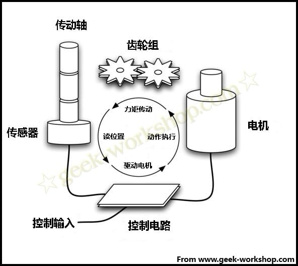
Servo (called Servo in English): It is a set of automatic control systems consisting of a DC motor, reduction gear set, sensor, and a control circuit. By sending a signal, the output axis rotation angle is specified.
Servo generally has a maximum rotation angle (such as 180 degrees.) The difference with ordinary DC motors is mainly in that DC motors rotate in a circle, and servos can only rotate within a certain angle, not in a circle (digital servos can switch between servo mode and motor mode without this problem).
THE ordinary DC motor can not feedback the rotation angle information, while the servo can do it. The applications are also different, as ordinary DC motors are generally used for powering the whole rotation, while servos are used to control the rotation of an object at a certain angle (such as the joints of a robot).
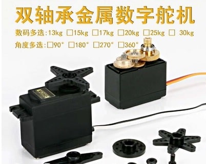
Servos come in a dazzling variety of shapes and sizes and can be roughly divided into the following categories (as shown in the figure)
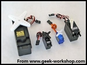
The one on the far right is a common standard servo, the two small ones in the middle are micro servos, and the lanky one on the left is a large-torque servo. These servos are all controlled by three wires.
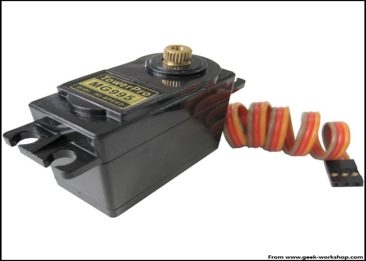
The following servos are commonly used for making robots, and each of them is fixed in a different way. If you change from one model to another, the whole mechanical structure needs to be redesigned.
The first one is MG995, which has the advantages of cheap price, metal gears, and good durability. The disadvantage is that the torque is relatively small, so the load can not be too large, if you do bipedal robots and the like, this servo is not very suitable, because the legs are too much force. Doing ordinary six-legged, or robotic is still good.
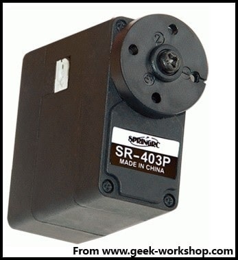
The second is SR 403, this servo is found by the net friend xqi2 because using the MG995 to do bipedal robot is shaking too much. After testing, the SR 403 makes a good bipedal robot, and at least not shaking. The advantage is the torque is large, all-metal gears, the price is also quite cheap, the disadvantage is that the workmanship is very cottage. Another disadvantage is waiting for feedback.
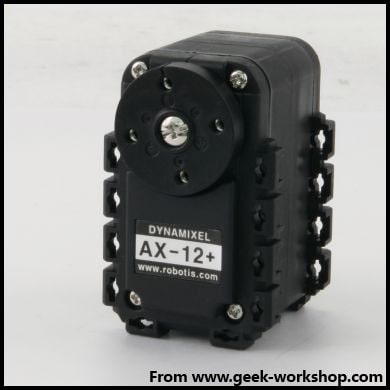
The third is the legendary digital servo AX12+, this is a special servo for the tried and tested robot. In addition to the high price, the use of RS485 serial communication (the control board will have to change the digital servo dedicated control board), the other is all advantages.
The following diagram is an exploded view of a common analog servo, whose components are mainly gear sets, motors, potentiometers, motor control boards, and housings.
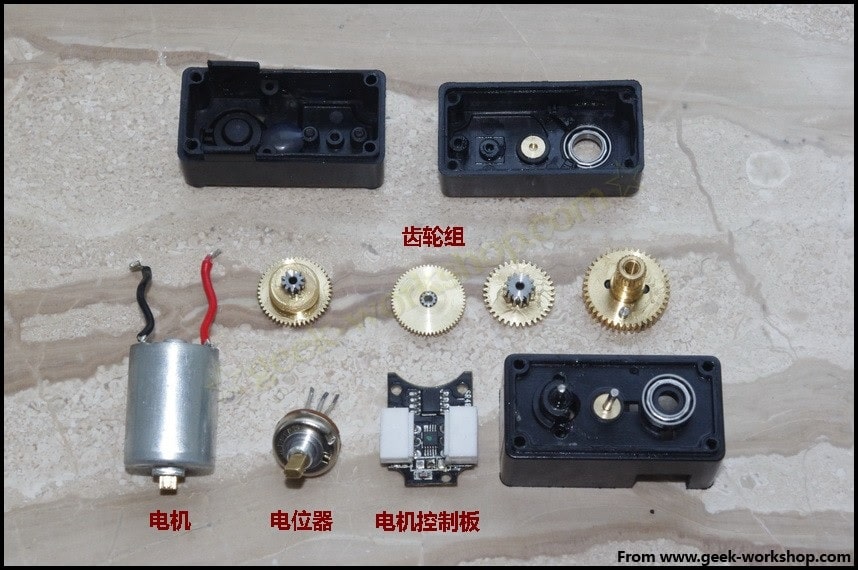
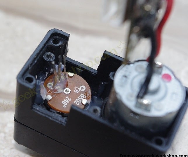
A motor control board is mainly used to drive the motor and receive information back from the potentiometer. The motor is the source of power, this does not need too much explanation.
The role of the potentiometer here is mainly to send the signal back to the motor control board through the change of resistance which is generated by its rotation so that it can judge whether the output axis angle is output correctly.
The role of the gear set is mainly to amplify the force so that the small power motor can generate large torque.
The bottom shell of the servo can be seen after dismantling, mainly the motor and control board.
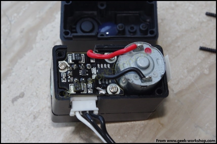
The bottom of the control board is the potentiometer that is connected to the control board after picking it up.
Looking at the motor and potentiometer from the top, the first stage amplifier gear is directly connected to the motor gear.
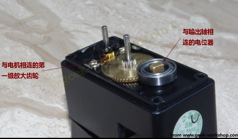
After being amplified by the first stage gear, it then passes through the second, third, and fourth stage amplifying gears before finally being output through the output axis.
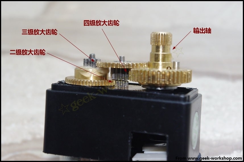
Through the above two pictures can be clearly seen, this servo is a 4-stage gear amplification mechanism, a small power is amplified through layer by layer so that a small motor can have 15KG of torque.
The servo control method :
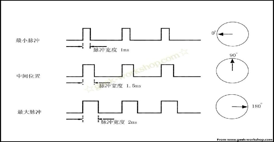
The servo system of the servo is controlled by variable width pulses, and the control line is used to transmit the pulses. The parameters of the pulse are minimum, maximum, and frequency. Generally, the reference signal of the servo is 20ms in period and 1.5ms in width. And the position defined by this reference signal is the middle position.
The servo has a maximum rotation angle, and the middle position is defined as the exact same amount from this position to the maximum angle as the minimum angle.
The most important point is that the maximum rotation angle may not be the same for different servos, but the width of the pulse at its middle position is certain, which is 1.5ms. As follows:
The angle is generated by a continuous pulse from the control line. This method of control is called pulse modulation. The length of the pulse determines how far the servo will turn. For example, a 1.5-millisecond pulse will go to the middle position of rotation (for a 180° servo, it is the 90° position).
When the control system sends a command to let the rudder move to a certain position and let it keep this angle, this time the influence of external forces will not let its angle change, but this has the upper limit, the upper limit is its maximum torque.
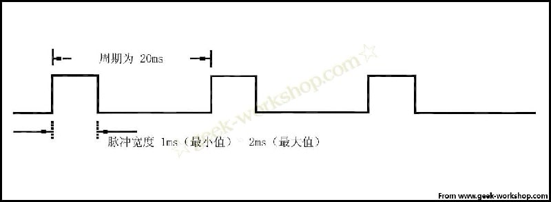
Unless the control system keeps sending out pulses to stabilize the angle of the servo, the angle of the servo will not remain unchanged. When the servo receives a pulse that is less than 1.5ms, the output axis will counterclockwise rotate a certain angle with the middle position as the standard. The opposite case is received pulses greater than 1.5ms.
Different brands, or even different servos of the same brand, will have different maximum and minimum values. Generally, the minimum pulse is 1ms and the maximum pulse is 2ms. As follows:
Small summary:
First of all, the servo leads, generally for three-wire control (No contact with a servo that is not a three-wire control), red for power, brown for ground, yellow for the signal. When controlling the servo, you need to constantly give PWM waves so that the servo has torque at a certain angle.
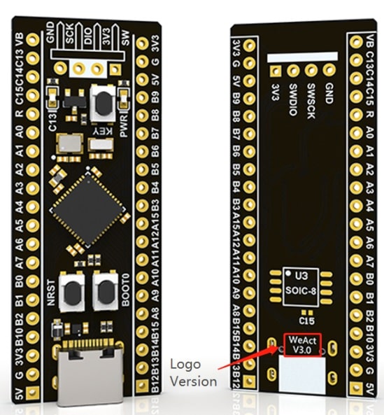
STM32 core board:
The microcontroller program uses the firmware library to program the STM32CUDEMX.
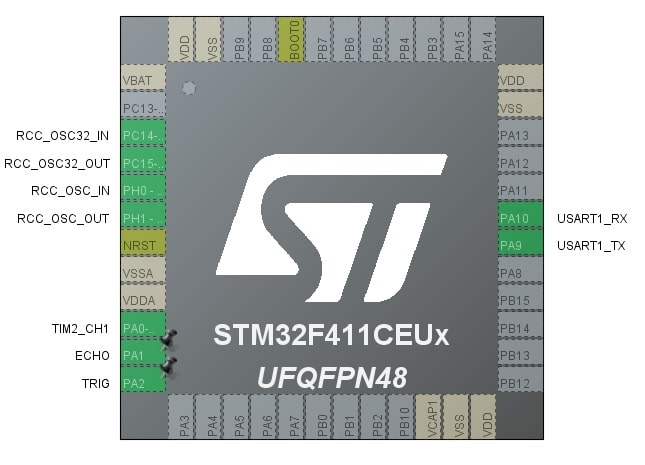
Pinout diagram:
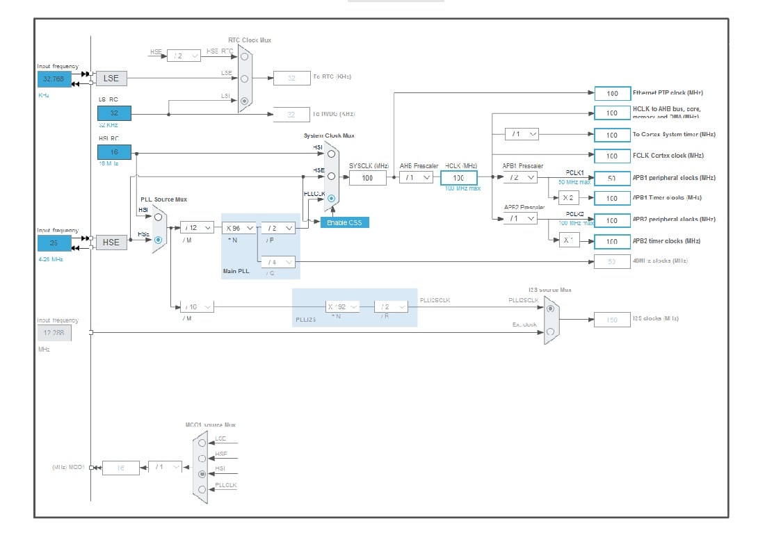
stm32 clock configuration:
Hardware connection:
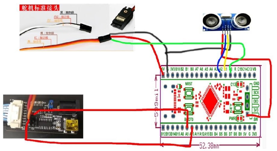
Schematic diagram of the connection between ultrasound and servo:
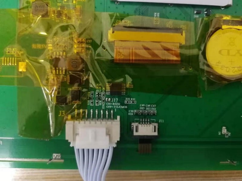
The J17 jumper on the back of the STONE screen is disconnected and selected to the TLL level and the microcontroller communicate:
Import GUI-generated files into the touch screen:
Source code analysis:
The microcontroller uses serial port 1 and touch screen communication, using a baud rate of 115200.
void MX_USART1_UART_Init(void)
{

    huart1.Instance = USART1;
    //Baud rate setting  huart1.Init.WordLength = UART_WORDLENGTH_8B;
    huart1.Init.BaudRate = 115200;
    huart1.Init.StopBits = UART_STOPBITS_1;
    huart1.Init.Parity = UART_PARITY_NONE;
    huart1.Init.Mode = UART_MODE_TX_RX;
    huart1.Init.HwFlowCtl = UART_HWCONTROL_NONE;
    huart1.Init.OverSampling = UART_OVERSAMPLING_16;
    if (HAL_UART_Init(&huart1) != HAL_OK)
    {
        Error_Handler();
    }
}
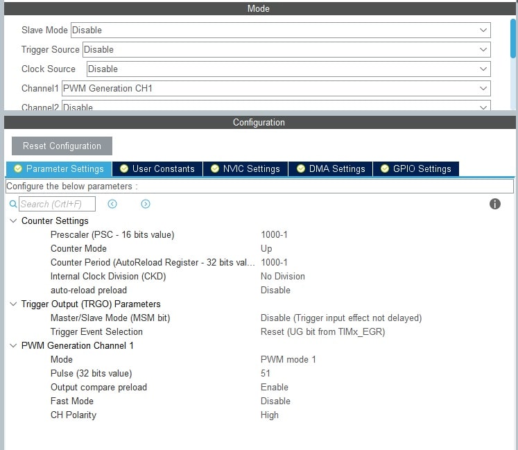
The servo driver is driven by using the microcontroller with its own PWM generator, configured as follows:
/* TIM2 init function */
void MX_TIM2_Init(void)
{
    TIM_MasterConfigTypeDef sMasterConfig = {0};
    TIM_OC_InitTypeDef sConfigOC = {0};

    htim2.Instance = TIM2;
    htim2.Init.Prescaler = 1000-1;
    htim2.Init.CounterMode = TIM_COUNTERMODE_UP;
    htim2.Init.Period = 1000-1;
    htim2.Init.ClockDivision = TIM_CLOCKDIVISION_DIV1;
    htim2.Init.AutoReloadPreload = TIM_AUTORELOAD_PRELOAD_DISABLE;
    if (HAL_TIM_PWM_Init(&htim2) != HAL_OK)
    {
        Error_Handler();
    }
    sMasterConfig.MasterOutputTrigger = TIM_TRGO_RESET;
    sMasterConfig.MasterSlaveMode = TIM_MASTERSLAVEMODE_DISABLE;
    if (HAL_TIMEx_MasterConfigSynchronization(&htim2, &sMasterConfig) != HAL_OK)
    {
        Error_Handler();
    }
    sConfigOC.OCMode = TIM_OCMODE_PWM1;
    sConfigOC.Pulse = 51;
    sConfigOC.OCPolarity = TIM_OCPOLARITY_HIGH;
    sConfigOC.OCFastMode = TIM_OCFAST_DISABLE;
    if (HAL_TIM_PWM_ConfigChannel(&htim2, &sConfigOC, TIM_CHANNEL_1) != HAL_OK)
    {
        Error_Handler();
    }
    HAL_TIM_MspPostInit(&htim2);

}
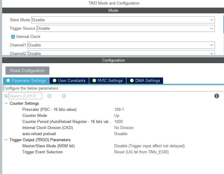
Sensor ranging is controlled by using interrupts and configured as follows:
Ranging procedure:
//Calculating distances in the timer
void HAL_GPIO_EXTI_Callback(uint16_t GPIO_Pin)
{
    if(GPIO_Pin == GPIO_PIN_1)
    {
        //Start measurement
        if( (HAL_GPIO_ReadPin(ECHO_GPIO_Port,ECHO_Pin) == 1) && (bit_bit == 1) )
        {
            __HAL_TIM_SetCounter(&htim3,0);//Clear Timer
            HAL_TIM_Base_Start_IT(&htim3);//Open Timer
        }//Stop measurement
        else if( (HAL_GPIO_ReadPin(ECHO_GPIO_Port,ECHO_Pin) == 0) && (bit_bit == 1) )
        {
            HAL_TIM_Base_Stop_IT(&htim3);//Close Timer
            cm = msHcCount*1000;
            cm += __HAL_TIM_GetCounter(&htim3);	//Read Timer us
            __HAL_TIM_SetCounter(&htim3,0);	//Clear Timer
            msHcCount = 0;
            bit_bit = 0;
        }
    }
}
The microcontroller packages the measured data and sends it to the touch screen:
void HOME(void* argument)
{
    /* USER CODE BEGIN HOME */
    /* Infinite loop */

    uint8_t data_ico[24] = {0xA5, 0x5A, 0x14, 0x85, 0x00, 0x00,
                            0x00, 0x00, 0x00, 0xff, 0xff, 0xff,
                            0xff, 0xff, 0xff, 0xff, 0xff, 0xff,
                            0xff, 0xff, 0xff, 0xff, 0xff
                           };
    uint8_t k = 0;
    uint16_t j = 0, bit = 0;

    for (;;)
    {
        if (bit_state)
        {
            if (bit == 0)
            {
                j++;
            }
            else
            {
                j--;
            }

            if (bit == 0 && j >= 180)
            {
                bit = 1;
            }
            else if (bit == 1 && j <= 0)
            {
                bit = 0;
            }
        }
        jiaodu = j;

        // x is Horizontal
        // y is Vertical
        for (k = 0; k < 7; k++) // Refresh the ico icon
        {
            if (Y >= 600)
                Y = 600;
            if (Y < 170)
                Y = 170;

            data_ico[5] = X >> 8; // x
            data_ico[6] = X;
            data_ico[7] = Y >> 8; // y
            data_ico[8] = (Y + k) & 0x00ff;
            UART1_Send_Array(data_ico, 23);
        }

        // Refresh display distance
        data_send[4] = 0x06;
        data_send[5] = 0xc8;
        data_send[6] = juli >> 8;
        data_send[7] = juli;
        UART1_Send_Array(data_send, 8);

        // Refresh pointer angle
        data_send[4] = 0x00;
        data_send[5] = 0x01;
        data_send[6] = 0x00;
        data_send[7] = jiaodu;
        UART1_Send_Array(data_send, 8);

        //		data_page[5] = 1;
        //		UART1_Send_Array(data_page,6);//Switching pages, for refreshing

        vTaskDelay(pdMS_TO_TICKS(10));
        osDelay(1);
    }
    /* USER CODE END HOME */
}
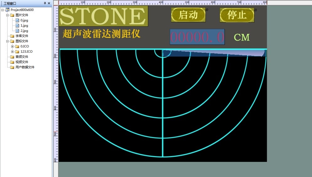
GUI uses the Tool Software 4.3 tool to edit the page, Import the prepared jpg image into the software. You can check the stoneitech website to download the software.
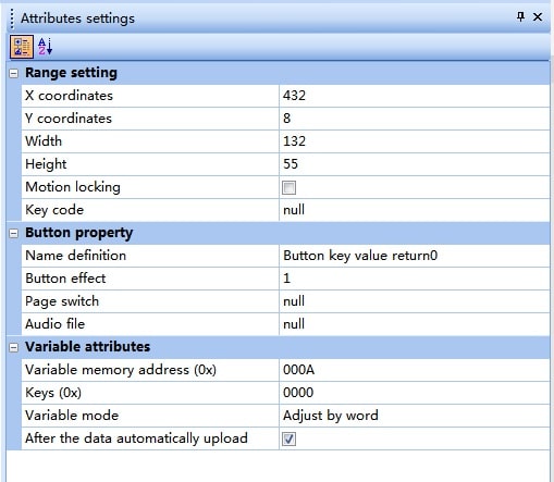
Setting start button:
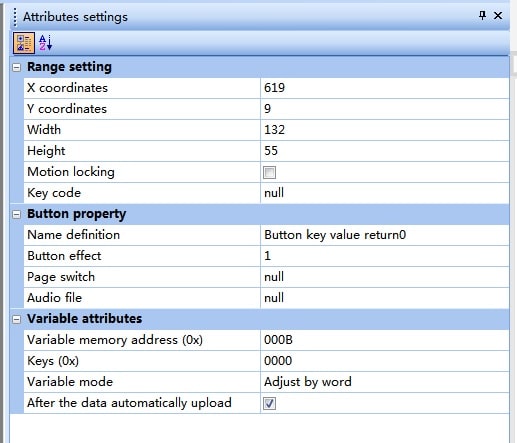
Setting stop button:
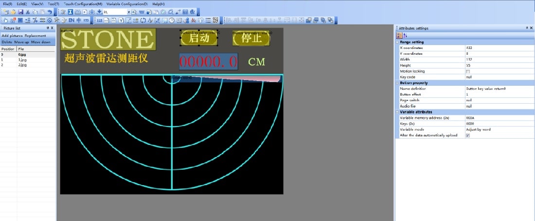
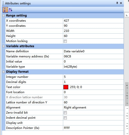
Digital display box:
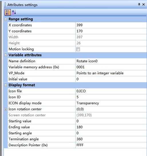
Rotating pointer configuration:
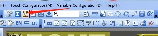
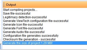
After setting up the display control, compile it first to see if there are any errors:
Lower status output box, no errors, and no warnings:
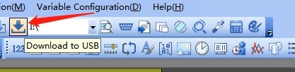
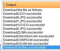
Connect the USB socket on the back of the touch screen, click to download:
Download completed:
About Author:
I am Grey li, currently, I am working as a senior hardware engineer in a company, I am familiar with various microcontrollers (ESP, STM32, PLC, PIC AVR, and 8051), I have 8 years of working experience in project engineering development.
Here is my social media profile Twitter:
https://twitter.com/salanianco;
Recommended Post
- Fuel Monitoring system using 8051.
- Interfacing ADC0804 with 8051 microcontroller.
- Led blinking program in c for 8051.
- Interfacing of a switch and led using the 8051
- Interfacing of Relay with 8051 microcontroller
- Moving message display on LCD using 8051
- LCD 4-bit mode c code for 8051.
- Create LCD custom characters for 16×2 alphanumeric LCD
- Interfacing of keypad with 8051
- Electronic digital lock using the 8051
- Interfacing of EEPROM with 8051 microcontrollers using I2C
- Embedded c interview questions.
- 8051 Microcontroller Pin Diagram and Pin Description.