It is very interesting to learn how to interface the ADC with the 8051 microcontroller. Like another microcontroller (PIC, Arduino Avr microcontroller ..etc) 8051 microcontroller does not have built-in ADC. So if you want to use LM35 temperature sensor to measure temperature with 8051 then you have to interface external ADC with 8051 microcontrollers.
In this article, you will learn how to interface, analog to digital converter with 8051 microcontrollers. Basically ADC is used to convert the analog signals into a digital signal. The analog signal can be the output of some sensor and it converts by ADC in digital format for further processing.
So for easy understanding here I am taking a temperature sensor as analog input and ADC0804 to convert the analog input in digital format. Here I will use converted digital data for 8051 and display it on 16×2 alphanumeric LCD.
Few features of Adc0804:
1. 8-bit resolution.
2. 0-5V input voltage range.
3. Built-in clock generator.
4. Differential analog voltage inputs.
5. No zero adjustment.
6. The voltage at Vref/2 (pin9) can be externally adjusted to convert smaller input voltage spans
to full 8-bit resolution.
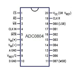
Pin Diagram of Adc0804:
Before going to explain the pin diagram of ADC0804. I want to explain the few terms related to ADC which are extremely important to know.
Resolution:
The resolution of an ADC is how accurately it will sample (convert) the analog signals into digital values (i.e. 0s and 1s). Higher is the resolution then greater will be the accuracy.
Step size:
It is the minimum voltage change that measures by the ADC. In other words, you can say that
the step size is the voltage difference between one digital level (i.e. 0001) and the next digital level (i.e. 0010 or 0000). For example, If a 4bit ADC has the step size 1 volt then if we will give the 1 volt as input the output will be 0001.
Now let see the pic configuration of ADC0804,
CS: Chip Select
It is an active low pin and is used to activate ADC0804
RD: Read Pin
It is an input pin and active at low. ADC stores the result in an internal register after the conversion of analog data. This pin helps to get the data out of the ADC0804. When CS=0, high to low pulse is given to RD pin, then digital output comes on the pins D0-D7
WR: Write Pin
It is an input pin and is active low which is used to initiate the ADC to start the conversion process.
When CS=0, WR makes a low to high transition, then ADC starts the conversion process.
CLK IN: Clock IN
This is an input pin that is connected to an external clock source.
INTR: Interrupt
This is an output pin and is active low. When the conversion is over, this pin goes low.
Vin+: Analog Input
Analog input to ADC.
Vin-: Analog Input.
Analog input connected to the ground.
AGND: Analog Ground
Connected to the ground.
Vref/2: Reference Voltage
It is used for the reference voltage. If this pin is not connected (open), then default reference voltage is 5v and the analog input voltage is in the range of 0 to 5 volts. We can reduce the step size using the reference pin.
DGND: Digital Ground
Connected to the ground.
D7-D0: Output Data Bits
Output bits of binary data.
Dout = Vin / step size
Dout = digital data output (in decimal),
Vin = analog voltage, and
step size (resolution) = it is the smallest change in voltage
CLKR: Clock Reset
To reset the clock.
Vcc: Positive Supply
The power supply of ADC.
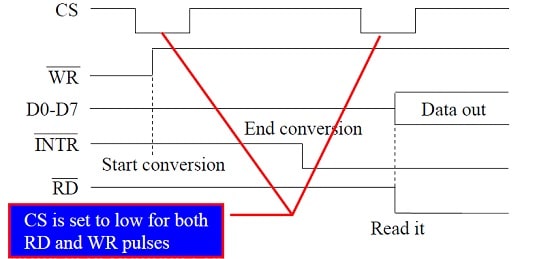
Conversion Steps of ADC0804
Below I have mentioned the few steps for data conversion which must be followed by the ADC804 chip.
1. Make CS = 0.
2. Send a low-to-high pulse to pin WR to start the conversion.
3. Monitor the INTR pin. If INTR is low, the conversion is finished but if the INTR is high, keep polling until it goes low.
4. After the INTR has become low, we make CS = 0 and send a high-to-low pulse to the RD pin to get the data out of the ADC804.
Let see an example code where I am interfacing ADC0804 with an 8051 microcontroller. In this example, I am using the LM35 temperature sensor and displaying the temperature on the 16×2 alphanumeric LCD.
#include <REGX51.H>

// Adc
#define ADC_DATA P1
sbit ADC_READ=P3^3;
sbit ADC_WRITE=P3^4;
sbit ADC_INTR=P3^5;


// Lcd
#define HIGH 1
#define LOW 0
#define LCD P2
sbit RS =P3^0;
sbit EN =P3^1;

//Prototype for ADC
unsigned char adcConvert();
void DisplayTempOnLcd(unsigned char adcData);

//Prototype for Lcd
void lcdCommand(const char command);
void displayOnLcd(const char *pszMessage);
void lcdStart(void);
void delay(unsigned int);


/*Function to write command on Lcd*/
void lcdCommand(const unsigned char command)
{
    LCD = command;
    RS = 0;
    EN  = 1;
    delay(300);
    EN=0;
}

void lcdData(const unsigned char dataPrint)
{
    LCD = dataPrint;
    RS=1;
    EN=1;
    delay(400);
    EN=0;
}
/*Function to Display string on Lcd*/
void displayOnLcd(const char *pData)
{
    while(*pData)
    {
        lcdData(*pData);
        ++pData;
        delay(300);
    }
}
/*Function to Provide delay*/
void delay(unsigned int time)
{
    unsigned int i;
    for(i=0; i<=time; i++);
}

/*Initialize the LCD*/
void lcdStart(void)
{
    delay(50);
    lcdCommand(0x01);
    delay(50);
    lcdCommand(0x80);
    delay(50);
    lcdCommand(0x0C);
}

unsigned char adcConvert()
{
    unsigned char adcData = 0x00;
    ADC_INTR = HIGH;
    ADC_READ  = HIGH;
    ADC_WRITE = HIGH;
    //Conversion Start
    ADC_WRITE = LOW;
    delay(50);
    ADC_WRITE = HIGH;
    while(ADC_INTR==HIGH)
    {
        //empty
    }
    delay(50);
    //Read Adc data
    ADC_READ = LOW;
    adcData = ADC_DATA;

    return(adcData);
}

void DisplayTempOnLcd(unsigned char adcData)
{
    int i=0,j =0;
    unsigned char adcValueByte[10] = {0};
    unsigned char tmpAdcData = adcData;
    while(tmpAdcData > 0)
    {
        adcValueByte[i++]=tmpAdcData%10;
        tmpAdcData =tmpAdcData/10;
    }
    for(j= (i-1); j>=0; --j)
    {
        lcdData(adcValueByte[j]+48);
    }
}


int main()
{
    unsigned char adcData = 0x00;
    unsigned char tmpAdcData = 0x01;
    while(1)
    {
        adcData = adcConvert();
        //true when temp change
        if(adcData != tmpAdcData)
        {
            //update temp variable
            tmpAdcData = adcData;
            lcdStart();
            displayOnLcd("TEMP:");
            DisplayTempOnLcd(adcData);
        }
    }

    return 0;
}
Recommended Post
- Led blinking program in c for 8051.
- Interfacing of switch and led using the 8051
- Interfacing of Relay with 8051 microcontroller
- Moving message display on LCD using 8051
- LCD 4-bit mode c code for 8051.
- Create LCD custom characters for 16×2 alphanumeric LCD
- Interfacing of keypad with 8051
- Electronic digital lock using the 8051
- Interfacing of EEPROM with 8051 microcontrollers using I2C
- Embedded c interview questions.
- 8051 Microcontroller Pin Diagram and Pin Description.