In this blog post, we will explore the I2C (Inter-Integrated Circuit) communication protocol in detail. You will learn how it works, including its hardware configuration, frame structure, and data transfer mechanism between devices. We will also explore why I2C is a preferred choice for chip-to-chip communication. We will also cover commonly used terms in I2C to help you build a solid foundation. Let’s start with a brief introduction.
I2C Protocol Introduction:
I2C is a widely used serial communication protocol that enables chip-to-chip communication using just two wires (Data and clock). Alongside UART and SPI, it’s one of the core protocols used in embedded systems.
It developed by Philips in the 1980s, I2C stands for Inter-Integrated Circuit. It was created to simplify communication between integrated circuits on the same PCB and has since become an industry standard supported by various chip manufacturers.
One of I2C’s standout features is its multi-master and multi-slave capability. While multiple devices can be connected on the same bus, communication is always initiated by the master. In multi-master setups, only one master can control the bus at any given time.
Note: Now days most microcontrollers come equipped with an I²C peripheral for communication with external devices. Many also support DMA (Direct Memory Access) to offload data transfers from the CPU, improving performance and reducing processing load.
What is I2C Communication Protocol?
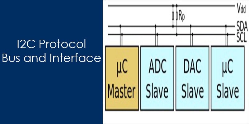
I2C (Inter-Integrated Circuit) is a serial communication protocol widely used to connect low-speed peripherals like LCD, EEPROMs, ADCs, RTCs, and various sensors. It enables data transfer between a master device (typically a microcontroller) and one or more slave devices over just two wires: a data line (SDA) and a clock line (SCL).
Due to its two-wire design, I2C is often referred to as a two-wire communication protocol. The SDA line carries the data, while the SCL line carries the clock signal used to synchronize communication between the master and slave devices.
Both SDA and SCL lines are bidirectional, meaning they can be used for sending and receiving signals. This bidirectional nature is essential for the protocol’s half-duplex communication style, allowing data to flow in both directions (but not simultaneously). The lines are typically open-drain and require pull-up resistors to maintain proper logic levels.
I2C is a half-duplex protocol, meaning data transmission happens in one direction at a time. The master initiates communication and can either transmit data to or request data from a slave device.
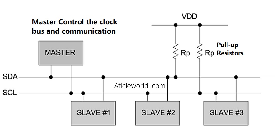
The clock bus is used to control the data transfer, and it synchronizes the master and slave together. The master controls the clock signal, making I2C a synchronous serial communication protocol. However, in some scenarios, a slave device may hold the clock line low to delay communication—this is known as clock stretching. I will discuss it in this blog post.
Additionally, I2C is also the foundation for several related control bus architectures, such as:
- SMBus (System Management Bus)
- PMBus (Power Management Bus)
- IPMI (Intelligent Platform Management Interface)
You’ll often encounter I2C in embedded projects involving components like:
- I2C LCD displays
- Accelerometers
- Biometric sensors
- OLED screens
- And many other sensor modules
Why use I2C Protocol
Unlike asynchronous serial communication (such as UART), I2C is a synchronous protocol, meaning it relies on a shared clock line (SCL) generated by the master device. This shared clock ensures precise timing and synchronization between the master and all connected slave devices.
In contrast, UART-based communication is asynchronous—each device maintains its own clock. Any mismatch between the transmitter and receiver clocks can result in framing errors or data corruption, especially at higher baud rates or over long durations.
Another significant limitation of UART is that it typically allows only point-to-point communication—a single transmitter and a single receiver at a time. I2C overcomes this with support for multi-master and multi-slave configurations, enabling multiple devices to communicate over the same two-wire bus (SDA for data and SCL for clock). This makes it highly scalable and ideal for systems with several peripherals.
While UART can achieve relatively high speeds (often up to 230400 baud), it lacks the bus flexibility and device addressing capability that I2C provides. UART also generally requires additional hardware like a UART controller or chip.
When compared to SPI (Serial Peripheral Interface), I2C is slower and supports only half-duplex communication. However, I2C offers several advantages:
- It requires only two wires, reducing pin usage and simplifying PCB layout.
- It supports multi-master communication, which SPI does not.
- It allows addressable communication with multiple slave devices, which is not natively supported in SPI.
In many embedded applications—especially where multiple low-speed peripherals need to communicate over a shared bus—I2C provides an optimal balance of simplicity, scalability, and efficiency.
We’ve covered a detailed comparison between SPI and I2C in another article. If you’re interested, feel free to check it out: “SPI vs I2C“.
Let’s see some of the important features of the I2C communication protocol:
Feature of I2C Bus:
- In I2C only two buses are required for the communication, the serial data bus (SDA) and serial clock bus (SCL).
- Each component in the I2C bus is software addressable by a unique address, this unique address is used by the master to communicate with a particular slave.
- I2C supports 7-bit and 10-bit addressing structures to target a specific slave (device or IC) on the I2C bus.
- Always a master and slave relationships exist at all times in I2C Bus.
- In I2C, communication always started by the master by sending the start bit.
- During the communication, we get the acknowledgment bit after each byte.
- The I2C bus provides the ability of arbitration and collision detection.
- I2C is the 8-bit oriented serial bidirectional communication, there are the following speed mode supported by the I2C Bus.
| MODE | SPEED |
| Standard-mode | 100 kbit/s |
| Fast-mode | 400 kbit/s |
| Fast-mode Plus | 1 Mbit/s |
| High-speed mode | 3.4 Mbit/s |
Note: (Unidirectional bus) -> Ultra Fast-mode (UFm), with a bit rate up to 5 Mbit/s.
I2C Bus Physical Layer and Hardware Configuration:
The Inter-Integrated Circuit (I²C) bus is a synchronous, half-duplex, serial communication protocol that follows a master-slave architecture. It supports both multi-master and multi-slave configurations, though single master with multiple slaves is most commonly seen in embedded systems.
The I2C bus uses only two bidirectional lines:
- SDA (Serial Data Line) – for data transmission.
- SCL (Serial Clock Line) – for clock synchronization, generated by the master.
Both SDA and SCl lines are open drain, don’t worry let me explain about it.
Open-Drain Configuration and Pull-Up Resistors:
At the physical layer, both SDA and SCL lines are configured as open-drain (or open-collector in bipolar logic). This means that devices can only pull the line low and cannot drive it high. When no device is actively pulling the line low, the line must be pulled high externally using pull-up resistors.
Before we dive into why pull-up resistors are important, it’s crucial to understand why the open-drain configuration is used in the first place.
In the below section we will explain about its importance of pullup resistor but before it is important to know that why open drain?
🔍 What is open drain?
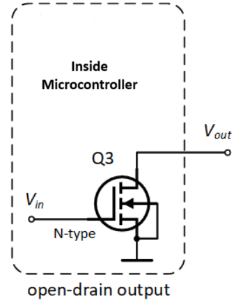
An open-drain output pin is driven by a single transistor—typically an NMOS —which can only pull the pin low (to ground). When the transistor is off, the output is in a high-impedance (Hi-Z) state, effectively floating, and requires an external pull-up resistor to bring the line high.
See the below image in which,
- Source is connected to GND.
- Gate is driven by a logic signal.
- Drain is the output — connected to the line you want to control (and pulled up externally).
🔄 Operation:
- Logical signal LOW (0) → NMOS ON → Line pulled to GND
- Logical signal HIGH (1) → NMOS OFF→ Line pulled up via resistor to VDD
🔍 Why open drain?
Open drain allows multiple devices to share the same bus without causing contention or short circuits. This setup enables what is called a wired-AND logic, where multiple devices can pull the line low safely.
- If any device pulls the line low → the line is low.
- If no device pulls the line low → the pull-up resistor restores the line to a high level.
This mechanism not only avoids signal contention but also enables features like multi-master arbitration and clock stretching—allowing multiple masters and slaves to communicate reliably over shared lines in a coordinated way.
Importance of Pull-Up Resistor Values:
Pull-up resistors are essential for proper voltage level restoration when the line is released. In simple words it restores the signal levels when no device is actively pulling the bus low. The resistor value has a direct impact on:
- ⏱️ Rise time of the signal (influenced by RC time constant)
- 📉 Maximum achievable clock frequency
- 🔋 Overall power consumption
📏 Typical Pull-Up Resistor Values:
Common pull-up values range from 1 kΩ to 10 kΩ, and the ideal value depends on bus capacitance, supply voltage, and speed mode:
🔹 Lower resistance (e.g., 1 kΩ) → Strong pull-up
- Faster rise time.
- Higher current consumption.
- Better for long buses or high-speed modes
🔹 Higher resistance (e.g., 10 kΩ) → Weak pull-up
- Slower rise time.
- Lower current draw.
- Suitable for shorter buses or lower speed modes
⚠️ Caution: If the resistor is too large, the line may not rise quickly enough, violating I2C timing specifications and leading to communication failures, especially in Fast-mode (400 kHz) or Fast-mode Plus (1 MHz).
🚀 In High-Speed or High-Capacitance Systems:
In high-speed applications or when the I2C bus has high capacitance (e.g., due to long traces or many devices), traditional resistive pull-ups might not be fast enough. In such cases, designers may use:
- Current sources instead of resistors.
- Bus accelerators or active pull-up circuits.
- Stronger pull-up resistors combined with carefully tuned drive strength
These methods help maintain sharp signal edges and reliable communication.
If you want to learn STM32 from scratch, you should follow this course “Mastering Microcontroller with Embedded Driver Development“. The course contains video lectures of 18.5-hours in length covering all topics like, Microcontroller & Peripheral Driver Development for STM32 GPIO, I2C, SPI, USART using Embedded C.

Enroll In Course
How I2C Communication Works?
I2C is a simple, robust chip-to-chip serial communication protocol that operates on a master-slave architecture. In any I2C transaction, communication is always initiated by the master device.
Here’s how it works step by step:
1. Start Condition:
Communication begins when the master generates a START condition by pulling the SDA line low while the SCL line is high.
2. Address Frame:
The master then sends a 7-bit or 10-bit slave address, followed by a Read/Write (R/W) bit, indicating whether it wants to read from or write to the slave.
3. Acknowledgment (ACK/NACK):
- If a slave with the matching address exists on the bus, it responds by pulling the SDA line low during the 9th clock cycle, sending an ACK (Acknowledgment) bit.
- If no slave recognizes the address, the master receives a NACK (Not Acknowledged) instead.
4. Data Transfer:
Once the slave acknowledges, the master continues the communication by sending or receiving data bytes, depending on the R/W bit. Each byte is followed by an ACK/NACK bit to confirm receipt.
5. Stop or Repeated Start Condition:
- After the data transfer is complete, the master generates a STOP condition (releasing SDA while SCL is high) to end the communication.
- Alternatively, the master can send a Repeated START if it wants to begin another transaction without releasing the bus.
🛠️ Note: After the START condition is issued, all slaves enter an attentive state, monitoring the bus to check if the address sent matches their own.
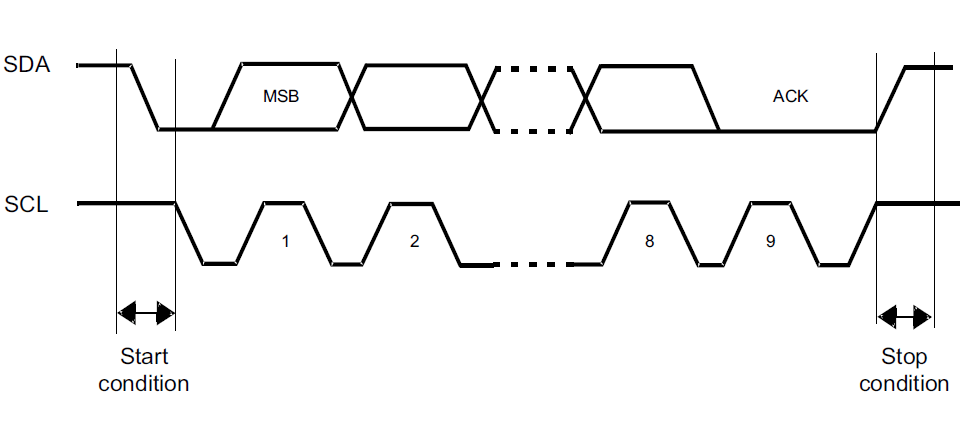
🧱 I2C Data Frame Structure:
I2C is a byte-oriented (8-bit) communication protocol, where each byte of data is followed by an acknowledgment (ACK) or no-acknowledgment (NACK) bit. In I2C, data is transferred in the form of messages, and each I2C transaction can consist of one or more messages. A message is defined by:
- A Start condition.
- One or more data frames.
- A Stop condition/ Or repeated start condition.
Optionally, the master can issue a repeated start condition instead of a stop, allowing it to retain control of the bus for sending another message. This is referred to as a “combined format” transaction.
📦 Structure of an I2C Message:
Each message consists of multiple frames:

1. Address Frame:
- Contains the 7-bit or 10-bit slave address
- Followed by a Read/Write (R/W) bit to indicate direction (0 for write, 1 for read)
2. Data Frames:
- Each data frame is 8 bits (1 byte) of payload.
- After each byte, the receiver (slave or master) sends an ACK or NACK to indicate successful receipt
3. Control Bits:
- Start Condition (initiates the communication).
- Stop Condition (ends the communication)
- Repeated Start (optional, used in combined message formats)
✅ The ACK/NACK bits are not part of the data byte—they are separate control bits that follow each byte of data.
The following section describes each part of the I2C data frame to provide a clear understanding of the I2C message format
Default Bus State:
By default, both the SDA (Serial Data Line) and SCL (Serial Clock Line) are held high due to external pull-up resistors, thanks to the external pull-up resistors. This high state indicates that the bus is idle and ready for communication.
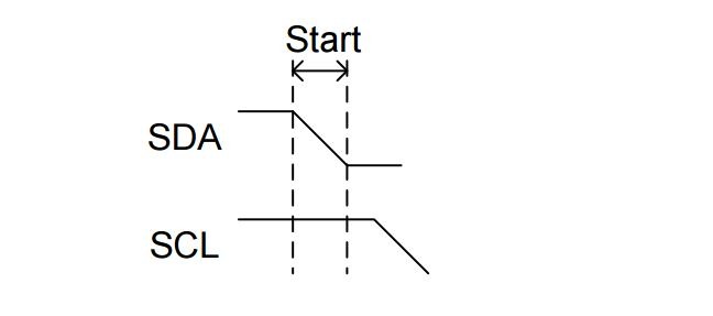
Start Condition:
In I2C, every communication begins with a Start Condition. This signal is essential for synchronizing communication between the master and slave devices on the bus. It is a specific signal that tells all devices on the bus that a communication session is about to begin.
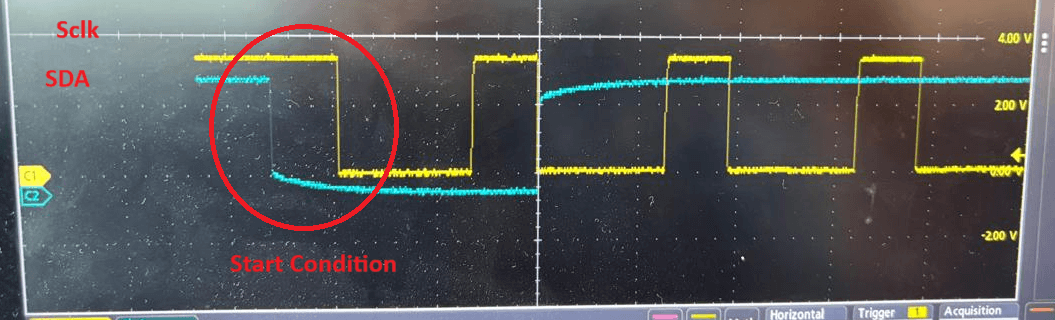
A Start Condition occurs when the SDA line transitions from HIGH to LOW while the SCL line remains HIGH. It used by the master to signal the beginning of communication on the bus.
This unique pattern cannot occur during normal data transmission and is recognized by all I2C-compatible devices as the beginning of a new message
🧠 Key Points to Remember:
- Start Condition => SDA goes low while SCL is high that means first pull SDA low then pull SCL low.
- The Start Condition must always be followed by a valid address frame.
- Always generated by the master.
- Marks the start of a message.
- Bus becomes busy until a Stop or repeated Start condition is sent.
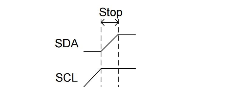
Stop Condition:
The STOP Condition is used by the master device to signal the end of communication on the I2C bus. When the master wants to end communication, it first ensures the SDA line transitions from low to high while the SCL line is still high.
A STOP Condition occurs when the SDA line transitions from LOW to HIGH while the SCL line remains HIGH. This specific pattern is recognized by all devices on the bus as the end of the current transaction.
🧠 Key Points to Remember:
- Stop Condition => SDA goes high while SCL is high; that means first SCL returns high then SDA returns high.
- Only the master can generate the STOP Condition.
- Once the STOP Condition is asserted, the I2C bus is considered idle or free. No clock signal.
- Slave devices return to their waiting state, ready for the next START Condition.
Repeated Start Condition:
The Repeated Start Condition is functionally similar to the Start Condition, but it occurs without releasing the bus (i.e., before a Stop Condition is issued). It allows the master to retain control of the bus and start a new message sequence immediately.
A Repeated Start is issued by the master by generating a Start Condition again while the bus is still busy (i.e., without sending a Stop Condition in between).
This is especially useful in scenarios where the master needs to change the direction of communication (e.g., from write to read) or access another slave without giving up control of the bus.
💡 Why is Repeated Start Important?
- It ensures atomic communication, avoiding interruption by other masters in a multi-master system.
- It’s also common in reading from registers—where the master first writes the register address, then issues a repeated start to read the data. Following is a very typical I2C read pattern.
-
- Master sends slave address + write bit.
- Sends register address it wants to read.
- Issues a repeated start (instead of stop).
- Sends slave address + read bit and reads the data.
-
📝 Note: Repeated Start is optional in single-master systems but becomes crucial in multi-master environments to prevent data collision or loss of control over the bus.
Address Frame:
Unlike SPI, I2C doesn’t use dedicated slave-select (SS) lines to choose a slave device. Instead, it uses an address-based communication mechanism, where each slave is assigned a unique address. This is why I2C is often referred to as an address-based bus protocol.
Every I2C communication starts with a Start Condition, followed by the Address Frame, which allows the master to specify which slave device it wants to communicate with. This address frame is always the first byte after the Start Condition.
I2C supports both 7-bit and 10-bit addressing schemes. The most common is the 7-bit address, where:
- The first 7 bits represent the slave address.
- The 8th bit (LSB) is the Read/Write (R/W’) bit:
-
- 0 = Write
- 1 = Read
-
Let’s see Structure of a Message (7-bit Address Example)
| Field: | S | I2C address field | R/W’ | A | I2C message sequences… | P | ||||||
| Type | Start | Byte 1 | ACK | Byte X etc…
Rest of the read or write message goes here |
Stop | |||||||
| Bit position in byte X | 7 | 6 | 5 | 4 | 3 | 2 | 1 | 0 | ||||
| 7-bit address pos | 7 | 6 | 5 | 4 | 3 | 2 | 1 | |||||
| Note | MSB | LSB | 1 = Read | |||||||||
| 0 = Write | ||||||||||||
This structure ensures that only the addressed slave responds, while all other devices remain idle on the bus. The slave that recognizes its address sends an ACK bit to the master to confirm readiness for communication.
🧠 Key Points to Remember:
- 7-bit addressing is most common (0x00 to 0x7F); 10-bit is less used.
- R/W bit is not part of the address; it’s appended during transmission.
- Reserved addresses (e.g., 0x00, 0x78–0x7F) should be avoided.
- Each I2C node on a Bus must have unique address. Address conflicts on the bus cause communication errors.
- Some devices allow configurable addresses via pins (0101A2A1A0) or software.
- Slave must ACK after receiving its address; no ACK means no response.
⏱ Clock and Data Timing Rules:
In I2C communication, 1 bit is transmitted per clock cycle, synchronized by the SCL (clock) line. For reliable data transfer, the timing relationship between SDA (data) and SCL (clock) lines must follow these important rules:
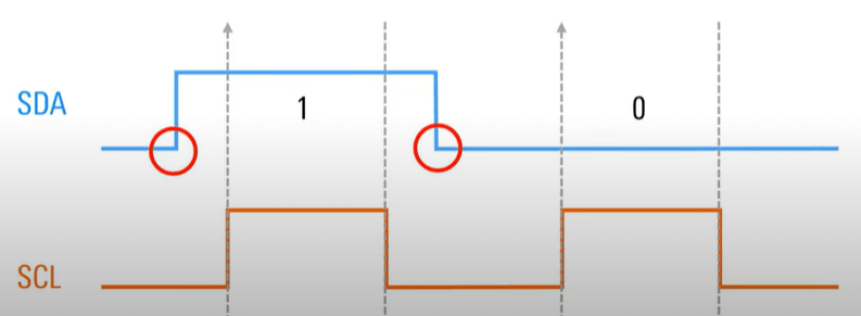
✅ SDA must remain stable when SCL is high.
➤ This is when the receiver latches the data bit.
✅ SDA should only change when SCL is low.
➤ This prevents data corruption and ensures clear transitions.
⚠️ Exceptions to this rule:
-
- Start Condition: SDA transitions from high to low while SCL is high.
- Stop Condition: SDA transitions from low to high while SCL is high.
- Repeated Start Condition: Another Start issued without a Stop.
✅ These timing rules define when data is considered valid and safe to read on the SDA line—this is referred to as the data valid period in I2C communication.
🔍 Note: Violating these timing rules can lead to data corruption, false start/stop detection, or miscommunication between devices.
ACK/NACK Bit
In the I2C protocol, every byte of data (whether it’s an address or data byte) is followed by a single bit known as the ACK (Acknowledge) or NACK (Not Acknowledge) bit. This bit is used by the receiver to inform the sender whether the byte was successfully received.
If the receiver successfully receives a byte, it pulls the SDA line low during the 9th clock cycle, which the sender interprets as an ACK. If the receiver does not acknowledge, it leaves the SDA line high, signaling a NACK.
🔍 When is a NACK generated?
A NACK can occur in several situations:
- No matching slave address: If the master sends an address and no slave on the bus matches it, the master receives a NACK because no device responds.
- Receiver not ready or busy: If a slave is temporarily unable to process data—due to internal processing, buffer overflow, or being in a different state—it may issue a NACK to indicate it can’t proceed.
- Unsupported command or invalid data: If a slave receives a command or data, it doesn’t understand or support, it may respond with a NACK.
- End of read transaction: When the master is reading from a slave, it sends a NACK after the final byte to signal the end of the read operation. This tells the slave that no more data is requested.
Read/Write Bit
As mentioned earlier, the address frame in I2C communication includes a single Read/Write (R/W) bit at the end. This bit indicates the direction of data transfer between the master and the slave device.
- If the R/W bit is ‘0’, it means the master wants to write data to the slave (i.e., transmit data).
- If the R/W bit is ‘1’, it means the master wants to read data from the slave (i.e., receive data).
This bit is crucial because it helps the addressed slave understand whether it should prepare to receive data from the master or send data back to the master. We’ll explore how this works in detail in the upcoming sections on read and write operations.
I2C write operation:
Before performing a write operation on the I2C bus, the master must first assert a Start condition, followed by transmitting the 7-bit slave address along with the write control bit (R/W bit = 0 for write).
If the transmitted address matches any slave device (e.g., an EEPROM) connected to the I2C bus, the slave responds with an ACK (acknowledge) bit. Upon receiving this ACK, the master sends the register address where it intends to write the data. The slave again acknowledges, indicating it is ready to receive the data.
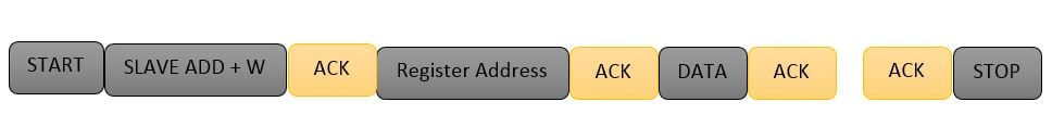

After the second acknowledgment, the master starts sending data bytes to the slave. Each byte is followed by an acknowledgment from the slave. If the master fails to receive an acknowledgment from the slave at any point, it can either:
- Assert a Stop condition to terminate the communication, or
- Assert a Repeated Start condition to attempt re-establishing communication.
Once all data bytes are successfully transmitted and acknowledged, the master ends the transaction by asserting a Stop condition.
I2C Read operation:
The I2C read operation is similar to the write operation, where the master first asserts a Start condition. After this, the master sends the slave address along with the Read control bit (i.e., R/W bit = 1 for read). If a device on the I2C bus recognizes this address, it responds with an ACK by pulling the SDA (data) line low.
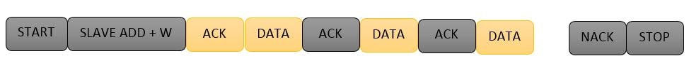
Once the ACK is received, the master releases the SDA line but continues to generate the clock pulses. At this point, the master becomes the receiver, and the slave becomes the transmitter.
During the read operation, the master sends an ACK after receiving each byte to inform the slave that it is ready to receive more data. After receiving the last expected byte, the master sends a NACK to indicate the end of the read operation, followed by a Stop condition to release the bus and terminate the communication.
⚠️ Important Notes:
- It is important to remember that in I2C, data is always transmitted Most Significant Bit (MSB) first. This rule applies to:
- Device addresses.
- Register addresses.
- Data payloads
- The I2C master can transmit or receive multiple bytes continuously between a Start and Stop condition.
All 8-bit data frames on the bus follow this MSB-first format.
🤝 Handshaking Process in the I2C Protocol:
In I2C for each byte, an acknowledgment needs to be sent by the receiver, this acknowledgment bit is proof that data is properly received by the receiver and it wants to continue the communication.
A master starts the communication to assert a start condition on the bus. After the start condition master is transmitted a 7-bit address with associated read or write bits ( here I am discussing a 7-bit address).
After the transmission of the address byte, the master releases the data lines to put the data line (SDA) in a high impedance state, which allows the receiver to give the acknowledgment bit.
If this transmitted address is matched with any receiver then it pulls down the SDA lines low for the acknowledgment and after the acknowledgment, it releases the data lines. The master generates a clock pulse to read this acknowledgment bit and continue the read or write operation.
If this transmitted address is not matched with any receiver then nobody is pull down the data lines low, master understands it is a NACK and in that situation, the master asserts a stop bit or repeated start bit for further communication.
In the I2C protocol, handshaking is achieved using acknowledgment (ACK) and not-acknowledge (NACK) bits. These bits play a crucial role in ensuring reliable communication between the master and slave devices.
📘 Key Concepts:
- For every byte transferred, the receiver must respond with an ACK to indicate successful reception and willingness to continue communication.
- If no ACK is received, it’s considered a NACK, which typically signals the end of communication or that the receiver is not ready.
🔁 Step-by-Step Handshaking Process:
1. Start Condition:
- The master initiates communication by asserting a Start condition on the I2C bus.
2. Address Transmission:
- The master sends a 7-bit slave address, followed by a Read/Write (R/W) bit. (This explanation uses the standard 7-bit addressing mode.)
3. Releasing the Data Line:
- After transmitting the address + R/W bit, the master releases the SDA line (puts it in high-impedance state), allowing the addressed slave to respond.
4. ACK from Slave:
- If a slave device recognizes its address, it pulls the SDA line low during the next clock pulse, signaling an ACK.
- After this, the slave releases the SDA line again.
- The master samples this ACK during the following clock cycle and proceeds with the data transfer.
5. No ACK (NACK):
- If no slave pulls the SDA line low (i.e., no device acknowledges the address), the line remains high.
- The master interprets this as a NACK.
- In response, the master may either:
- Issue a Stop condition to terminate communication, or
- Send a Repeated Start condition to attempt communication again.
Special cases in I2C:
The I2C protocol includes a few special scenarios that go beyond basic read/write operations. One such important scenario is clock synchronization, especially in a multi-master setup. Let’s explore it in detail.
Clock synchronization in I2C
Unlike RS-232 (which is asynchronous), I2C is a synchronous communication protocol, where the clock signal (SCL) is shared between the master and slave. Typically, the master generates the clock, but things become more interesting when multiple masters are present on the bus.
In a multi-master configuration, each master can initiate communication and generate its own SCL clock. However, since all devices share the same physical clock line (SCL), their clocks must be synchronized to avoid data corruption. This synchronization is handled automatically by the I2C bus using a technique called wired-AND logic.
How Clock Synchronization Works?
Let’s take an example where two masters, M1 and M2, try to communicate on the I2C bus at the same time:
- Master M1 generates a clock signal: clk1
- Master M2 generates another clock signal: clk2
- The actual clock signal observed on the SCL line is the logical AND of both clocks: SCL = clk1 & clk2
This behavior is due to the open-drain (or open-collector) configuration of the I2C lines. Devices can only pull the line low; the high state is achieved via pull-up resistors.
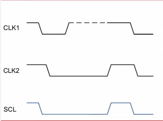
As a result, if either master pulls the SCL line low, the line stays low. The effective SCL clock on the bus is defined by the slowest master, i.e., the one holding the line low for a longer duration. This mechanism ensures clock stretching and synchronization across multiple masters.
Arbitration in I2C Bus:
Arbitration is a mechanism used in I2C to handle situations where multiple masters attempt to take control of the bus simultaneously. This is only relevant in multi-master configurations, and arbitration ensures that only one master wins and continues the communication without data corruption.
How Arbitration Works?
Arbitration is performed using the SDA (data) line, while the SCL (clock) line is already synchronized using wired-AND logic among all masters.
📘 Example Scenario
Consider a situation where two masters initiate communication at the same time:
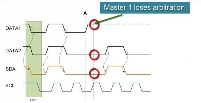
- Both masters assert a Start condition simultaneously and begin transmitting data.
- As long as both are sending the same data, they won’t detect any conflict.
- However, if one master sends a 1 on the SDA line while the other sends a 0, the SDA line will remain low (due to open-drain logic).
- The master that attempted to send a 1 but reads back a 0 on SDA realizes it has lost the arbitration.
- It immediately withdraws from the bus, allowing the winning master to continue communication.
📝 Important Note: The master that loses arbitration will wait until the bus becomes free (i.e., after a Stop condition) before attempting to communicate again.
✅ Key Takeaways
- Arbitration happens bit-by-bit during data transmission.
- It is non-destructive — the winning master continues without any corruption.
- The SDA line is used to detect conflicts.
- Only relevant in multi-master I2C systems
Clock stretching in I2C:
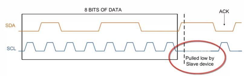
In the I2C protocol, clock stretching allows a slave device to pause communication by holding the SCL (clock) line low. Communication cannot continue until the slave releases the SCL line and allows it to go high again.
Why is Clock Stretching Needed?
While most I2C slaves can handle incoming data at the speed dictated by the master, some slaves may require additional time to process data—especially after receiving a byte. In such cases, the slave can pull the SCL line low, effectively pausing the communication. Once it is ready to continue, the slave releases the SCL line, allowing it to return high, and communication resumes.
⚠️ Important Notes:
- Clock stretching is initiated by the slave to signal the master to wait.
- SCL is always driven by the master, but the slave can temporarily hold it low to delay further clocking.
- Although clock stretching is part of the I2C specification, many slave devices do not implement this feature.
- However, every I2C master should support clock stretching to ensure compatibility with devices that use it.
✅ Advantages of I2C Communication Protocol:
The I2C protocol offers several advantages that make it a popular choice in many embedded and electronic applications:
1. Synchronous Communication:
- I2C is a synchronous protocol, meaning both the master and slave share the same clock signal. This eliminates the need for precise oscillators in slave devices.
2. Minimal Wiring:
- Only two wires are required — one for data (SDA) and one for clock (SCL) — reducing PCB complexity and saving I/O pins.
3. Flexible Data Rate:
- I2C allows the master to control the clock speed, enabling flexible transmission rates based on the application’s performance and power requirements.
4. Addressable Devices:
- Each device connected to the I2C bus has a unique address, allowing the master to communicate with multiple devices individually.
5. Master-Slave Architecture:
- I2C follows a well-defined master-slave communication model, making it organized and predictable.
6. Supports Multi-Master and Multi-Slave:
- The protocol can handle multiple masters and multiple slaves, with built-in features like arbitration and clock synchronization to manage bus access.
7. Advanced Features:
- I2C supports useful features like clock stretching, arbitration, and clock synchronization, enhancing reliability and robustness.
8. ACK/NACK for Error Handling:
- After every byte transfer, the receiving device sends an ACK (acknowledgment) or NACK (not acknowledged), allowing basic error detection and handling during communication.
⚠️ Limitations of the I2C Communication Protocol:
While I2C offers many advantages, it also comes with a few important limitations that may affect its suitability for certain applications:
1. Higher Power Consumption:
- Due to its open-drain topology, I2C consumes more power compared to other serial protocols like SPI, especially at higher speeds or longer buses.
2. Limited Communication Distance:
- I2C is best suited for short-distance communication (typically within the same PCB or a few centimeters), as signal integrity degrades over longer distances.
3. Slave Device Limitations:
- The number of slave devices that can be connected to the bus is limited by the total bus capacitance. The I2C standard specifies a maximum bus capacitance of 400 pF.
4. Restricted Speed Options:
- I2C supports only a few standard speed modes such as Standard Mode (100 kbit/s), Fast Mode (400 kbit/s), Fast Mode Plus (1 Mbit/s), and High-Speed Mode (3.4 Mbit/s), which may not be sufficient for high-throughput applications.
5. Speed Mismatch Issues:
- I2C allows devices of different speeds on the same bus. However, slower devices can delay the communication speed of the faster ones due to clock stretching, which may not be ideal in time-critical systems.
Conclusion
I2c is an easy and cheap communication protocol, It can be multi-master or multi-slave. In I2c we get the acknowledgment (ACK) and not acknowledgment(NACK) bits after each transmitted byte. Some disadvantage also attaches with I2C, it is a half-duplex communication and slow as compared to SPI (serial peripheral communication).
Recommended Post
- I2C vs SPI
- EEPROM Interfacing with PIC Microcontroller – I2C Based.
- RTC DS1307 Interfacing with PIC Microcontroller.
- Interfacing EEPROM with 8051 Microcontroller – I2C Based.
- Free Online programming tools.
- Can protocol Interview Questions.
- UART vs USART
- RS232 vs RS485
- 100 Embedded C Interview Questions
- 100 C Interview Questions.
- I2C Interview Questions
- Interview questions on bitwise operators in C
- C++ Interview Questions.
- 10 questions about dynamic memory allocation.
- File handling in C.
- Pointer in C.
- C format specifiers.
https://en.wikipedia.org/wiki/I%C2%B2C