
HDLC (High-Level Data Link Control) is a bit-oriented code-transparent synchronous data link layer protocol developed by the International Organization for Standardization (ISO). The standard for HDLC is ISO/IEC 13239:2002. HDLC provides both connection-oriented and connectionless service.
In HDLC, data is organized into a unit (called a frame) and sent across a network to a destination that verifies its successful arrival. It supports half-duplex full-duplex transmission, point-to-point, and multi-point configuration and switched or non-switched channels.
Original ISO standards for HDLC Protocol:
ISO 3309-1979 – Frame Structure
ISO 4335-1979 – Elements of Procedure
ISO 6159-1980 – Unbalanced Classes of Procedure
ISO 6256-1981 – Balanced Classes of Procedure
ISO/IEC 13239:2002, the current standard, replaced all of these specifications.
Types of stations for HDLC Protocol:
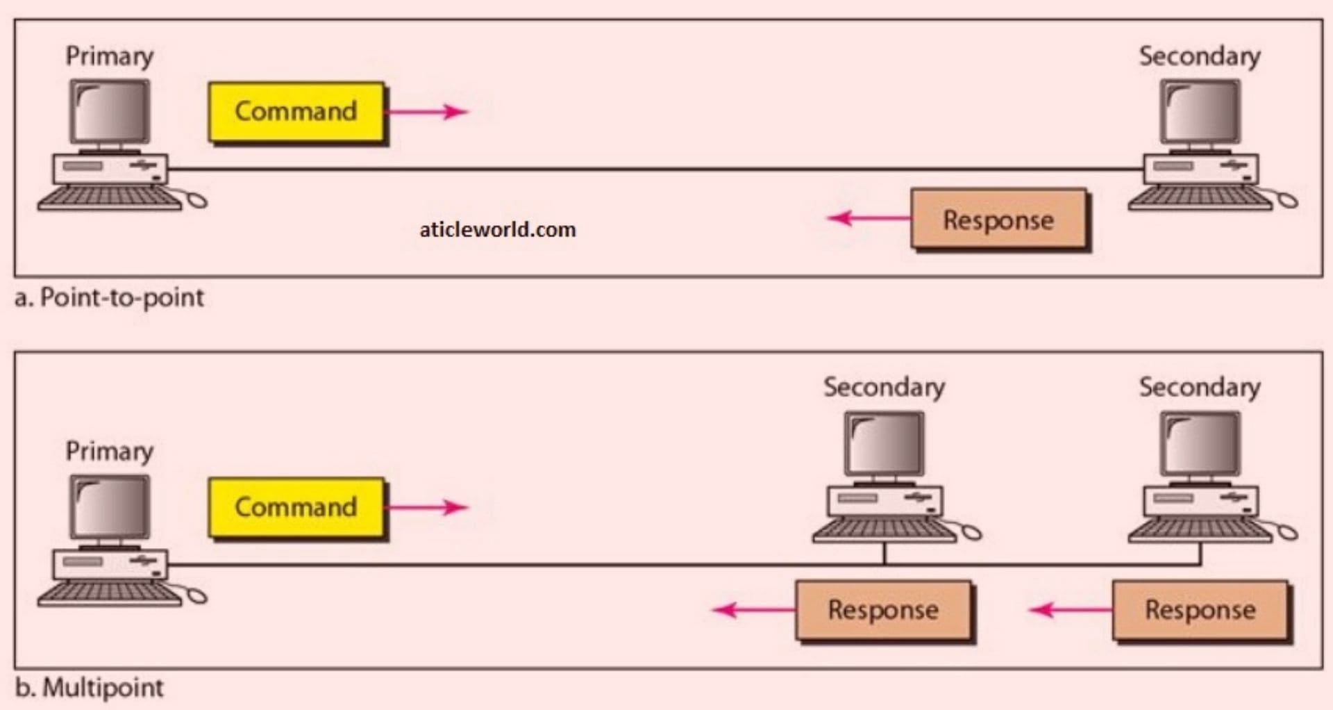
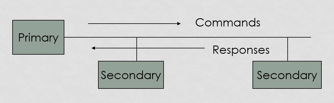
Primary station:
- It acts as a master and controls the operation.
- Handles error recovery.
- Frames issued by the primary station are called commands.
Secondary station:
- It acts as a slave and operates under the control of the primary station.
- Frames issued by a secondary station are called responses.
- The primary station maintains a separate logical link with each secondary station.
Combined station:
- Acts as both primary and secondary stations.
- It does not rely on others for sending data.
HDLC Data transfer modes:
HDLC communications session can use one of the following connection modes, which determine how the primary and secondary stations interact.
- Normal Response mode.
- Asynchronous Response mode.
- Asynchronous Balanced mode.
Normal Response mode:
A secondary station can only transmit when specifically instructed by the primary station in response to polling. It is used for both point-to-point and multipoint communications. It is an unbalanced configuration and good for multi-point links.
Asynchronous Response Mode (ARM):
- It is similar to NRM except that the secondaries can initiate transmissions without direct polling from the primary station.
- Asynchronous Response Mode (ARM) is an unbalanced configuration. It has a single primary station and multiple secondary stations.
Example of Unbalance Mode:
- Reduces overhead as no frames need to be sent to allow secondary nodes to transmit.
Asynchronous balanced mode (ABM):
- Asynchronous balanced mode (ABM) is a balanced configuration.
Example of balance mode

- Mainly used in point-to-point links, for communication between combined stations.
- Either station can initiate the data transfer at any time.
HDLC frame types:
Three fundamental types of HDLC frames may be distinguished:
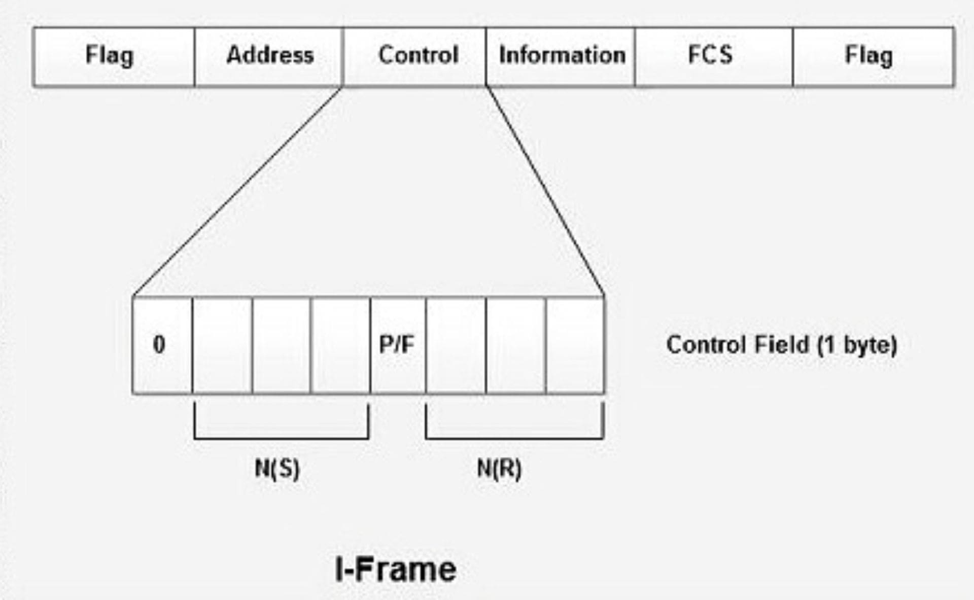
- Information frames, or I-frames, transport user data from the network layer. They can also include flow and error control information piggybacked on data.
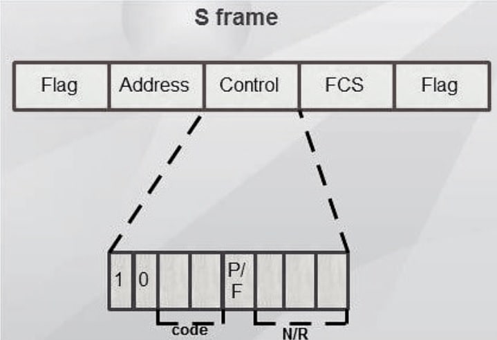
- Supervisory frames, or S-frames, are used for flow and error control whenever piggybacking is impossible or inappropriate, such as when a station does not have data to send. S-frames do not have information fields.
Some Example of S frames,
- RR — receive ready
- RNR — receive not ready
- REJ — reject on frame N(R)
- SREJ — selective reject on N(R)
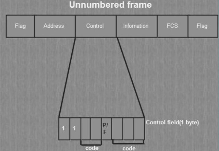
- Unnumbered frames, or U-frames, are used for various miscellaneous purposes, including link management. Some U-frames contain an information field, depending on the type.
Some Example of U frames,
- SNRM – Set Normal Response Mode
- SARM – Set Asynchronous Response Mode
- SABM – Set Asynchronous Balanced Mode
- UP – unnumbered polling
- UA – unnumbered acknowledge
- DISC – disconnect
- RD – request disconnect
- DM – Disconnect mode
Basic Frame Structure of HDLC
Here I have mentioned the basic frame structure of HDLC protocol.
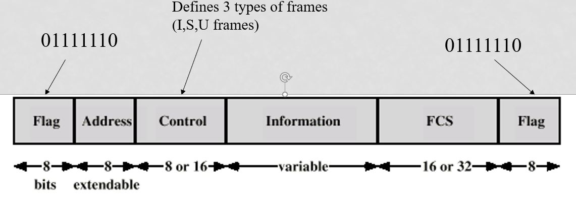
FLAG FIELD:
- There is no start and stop bits in the HDLC protocol. So it is used the delimiter 0x7e to indicate the beginning and end of the frame.
- Receiver hunts for flag sequence to synchronize
- If there are five consecutive 1s in the stream then bit stuffing used to avoid confusion with data containing 01111110.
- The transmitter inserts 0 bit after every sequence of five 1s with the exception of flag fields
- If the receiver detects five 1s it checks next bit.
- If 0, it is deleted.
- If 1 and the seventh bit is 0 (i.e., 10), accept as the flag.
- If sixth and seventh bits 1 (i.e., 11), the sender is indicating abort.
Address Field:
- Identifies secondary station that sent or will receive the frame.
- Usually 8 bits long.
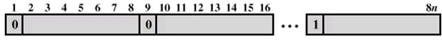
- It may be extended to multiples of 7 bits and the LSB of each octet indicates that it is the last octet (1) or not (0).
- Mainly used in multidrop link configuration, and not used in point-to-point.
- In the unbalanced configuration, every secondary is assigned a unique address. It contains the address of the secondary station in both command and response frames.
- In balanced mode, the command frame has a destination address and the response frame has to send the node’s address.
- All address bit is 1’s, then it is a broadcast address.
CONTROL FIELD:
In HDLC protocol control field is different for a different frame (I, S , U). HDLC uses the control field(C) to determine how to control the communications process. The control field in HDLC could be 8 or 16-bit wides to manage the flow.
This field contains the commands, responses and sequences numbers used to maintain the data flow accountability of the link, defines the functions of the frame and initiates the logic to control the movement of traffic between sending and receiving stations.
Let see the image to understand the control field.
| 7 | 6 | 5 | 4 | 3 | 2 | 1 | 0 | |
|---|---|---|---|---|---|---|---|---|
| N(R) Receive sequence no. |
P/F | N(S) Send sequence no. |
0 | I-frame | ||||
| N(R) Receive sequence no. |
P/F | type | 0 | 1 | S-frame | |||
| type | P/F | type | 1 | 1 | U-frame | |||
Note: The type field decides types of S and U frame in HDLC.
There are also extended (two-byte) forms of I and S frames. Again, the least significant bit (rightmost in this table) is sent first.
| 15 | 14 | 13 | 12 | 11 | 10 | 9 | 8 | 7 | 6 | 5 | 4 | 3 | 2 | 1 | 0 | ||
|---|---|---|---|---|---|---|---|---|---|---|---|---|---|---|---|---|---|
| N(R) Receive sequence no. |
P/F | N(S) Send sequence no. |
0 | Extended I-frame | |||||||||||||
| N(R) Receive sequence no. |
P/F | 0 | 0 | 0 | 0 | type | 0 | 1 | Extended S-frame | ||||||||
Frame Check Sequence (FCS):
Used for error detection. Here CRC16 or CRC32 is used for error detection.
Recommended Post
- Framing in Data Link Layer.
- Difference between HDLC and PPP.
- Difference between HTTP and HTTPS (HTTP vs HTTPS)
- SSL programming in C.
- Socket programming in C.
- Parse XML response in C without using the library.
- Create Http Get and Post request in C.
- File handling in C.
- I2C Communication protocol.
- Embedded C Interview Questions.
- Pointers in C.
- CAN Protocol Interview Questions.
- Bit-wise interview Questions in C.