Have you ever written REG |= BIT and assumed it was a safe way to set a bit? It certainly looks like a single operation. However, on an ARM Cortex-M processor, the CPU actually performs it in three steps: read, modify, and write. If an interrupt happens between these steps and updates the same register, your change can be lost.
In this article, we will see why this happens, understand what a race condition is, and learn how the LDREX and STREX instructions let you update a register atomically without disabling interrupts.
When working with GPIOs or other peripheral registers on an ARM Cortex-M microcontroller, you will often need to set or clear individual bits. Almost every embedded firmware developer has written code like this:
REG |= BIT;

   OR

REG &= ~BIT;
These statements look simple, and you will find them in almost every embedded project for setting or clearing bits in peripheral registers.
At first glance, they seem like single operations. So, it is easy to assume they are atomic and therefore safe to use, even when interrupts are enabled.
But what actually happens inside the processor when these statements execute?
Although each line is written as a single C statement, the processor does not execute it as a single instruction. Instead, it performs three separate steps:
- Read the current register value.
- Modify the required bit.
- Write the updated value back to the register.
This sequence is known as a Read-Modify-Write (RMW) operation.
The problem is that if an interrupt, another task, or any other execution context accesses the same register between the read and the write, one of the updates can be lost. This is called a race condition.
To solve this problem, ARM Cortex-M processors provide an elegant hardware mechanism using two special instructions: LDREX (Load Exclusive) and STREX (Store Exclusive).
In this article, we will first understand why Read-Modify-Write (RMW) operations are vulnerable to race conditions. Then we will see how ARM’s exclusive access mechanism solves this problem.
What Is a Read-Modify-Write Operation?
Consider the following statement used to enable a peripheral interrupt:
USART1->CR1 |= USART_CR1_RXNEIE;
Although it appears to be a single operation, the processor cannot modify just one bit directly. Instead, it performs three separate steps:
- Read the current register value.
- Modify the required bit.
- Write the updated value back.
Read Register
      │
      ▼
Modify Value
      │
      ▼
Write Register
This above-mentioned sequence is called a Read-Modify-Write (RMW) operation.
Normally, these three steps complete within a few CPU cycles. However, because they are separate operations, another execution context can interrupt the sequence before the final write occurs.
This is where problems begin.
Understanding the Race Condition:
Peripheral control registers are often accessed by both the main application and interrupt service routines (ISRs). If both try to update the same register at nearly the same time, a race condition can occur, causing one update to be lost without any warning or error.
Let’s consider a scenario,
Assume the control register is initially cleared:
CR1 = 0x00000000
Now suppose:
- The main application wants to enable the RXNE interrupt (RXNEIE).
- An ISR wants to enable the TXE interrupt (TXEIE).
Both operations update different bits in the same register, but each must first read the register, modify the required bit, and then write the updated value back.
What Actually Happens?
The problem occurs when the two operations overlap.
The main application reads the register, but before it can write the updated value back, an interrupt occurs.
The ISR executes completely, it reads the same register, sets its bit, and writes the new value. After the ISR finishes, the main application resumes and writes back the value it calculated earlier, unaware that the register has already been updated.
| Step | Main Application | ISR |
|---|---|---|
| 1 | Read CR1 = 0x00 |
|
| 2 | Read CR1 = 0x00 |
|
| 3 | Set TXEIE |
|
| 4 | Write CR1 = 0x02 |
|
| 5 | Set RXNEIE |
|
| 6 | Write CR1 = 0x01 |
Result:
CR1 = 0x01
Although the ISR successfully enabled TXEIE, its update was overwritten by the main application. The final register contains only RXNEIE, while TXEIE has been silently lost.
Why Does This Happen?
Both the main application and the ISR started with the same register value (0x00). Each modified its own copy independently and then wrote it back.
Since the main application wrote last, its value replaced the one written by the ISR. This is known as a lost update, one of the most common types of race conditions in embedded systems.
Note: The interrupt is not the real problem. The real problem is that a Read-Modify-Write operation is not atomic. If another execution context changes the register before the write completes, one of the updates can be overwritten.
At this point, you may be wondering about the solution. Don’t worry, the solution is explained in the following section.
Traditional Solution:
A common way to avoid a Read-Modify-Write race condition is to temporarily disable interrupts before updating the register. This small critical section prevents the ISR from interrupting the Read-Modify-Write sequence.
__disable_irq();          // Mask all configurable interrupts

CR1 |= RXNEIE;            // Read-Modify-Write operation

__enable_irq();           // Re-enable interrupts
Drawbacks:
Although disabling interrupts solves the race condition, it also affects the responsiveness of the entire system.
1. Increased Interrupt Latency:
While interrupts are disabled, every pending interrupt must wait until __enable_irq() is executed. Even interrupts unrelated to the shared register are delayed.
2. Blocks All Maskable Interrupts:
__disable_irq() sets the PRIMASK register, preventing all configurable-priority interrupts from executing. It does not distinguish between the interrupt accessing the shared register and other interrupts that may be time critical.
3. Reduced Real-Time Performance:
In real-time embedded systems, even short delays can introduce interrupt latency and timing jitter. If critical sections are used frequently, the accumulated delay can impact the overall responsiveness of the system.
ARM’s Hardware Solution: LDREX and STREX
Disabling interrupts is a straightforward way to make a Read-Modify-Write (RMW) operation atomic. However, this approach comes with an important drawback: no interrupt can be serviced while the critical section is executing. As the critical section grows longer, interrupt latency increases, reducing the responsiveness of a real-time system.
To overcome this limitation, ARM Cortex-M processors provide a hardware-assisted synchronization mechanism that allows software to perform atomic memory updates without globally disabling interrupts.
Cortex-M3, Cortex-M4, Cortex-M7, and Cortex-M33 processors introduce two special instructions for this purpose:
- LDREX (Load Exclusive)
- STREX (Store Exclusive)
Together, these instructions enable software to safely perform an atomic Read-Modify-Write operation while allowing the processor to continue servicing interrupts.
The Exclusive Monitor:
The key to this mechanism is a hardware component inside the processor called the Exclusive Monitor.
Unlike traditional locking mechanisms, the Exclusive Monitor does not lock the memory location or prevent other execution contexts from accessing it. Instead, it records that the processor has performed an exclusive load and tracks whether that exclusive reservation remains valid.
When STREX executes, the processor checks the Exclusive Monitor. If the reservation is still valid, the write succeeds. Otherwise, the write is aborted, and the software retries the operation.
This lightweight hardware mechanism enables efficient atomic operations while allowing interrupts to continue executing, making it well suited for real-time embedded systems.
How LDREX and STREX Work:
In the following section, we will examine the sequence of operations involved in performing an atomic update using the LDREX and STREX instructions.
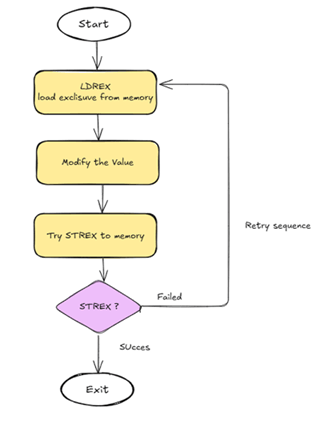
Load Exclusive (LDREX): Reads the current value from memory and establishes an exclusive reservation for the accessed address in the processor’s Exclusive Monitor.
Local Modification: The processor modifies the value in a general-purpose register. The memory location itself remains unchanged.
Conditional Store (STREX): The software attempts to write the updated value back to memory. Before performing the write, the processor checks whether the exclusive reservation established by LDREX is still valid.
Evaluate the Result:
- Reservation Still Valid: The write succeeds, memory is updated, and STREX returns 0.
- Exclusive Reservation Lost: The write is abandoned, memory remains unchanged, and STREX returns a non-zero value.
If the store fails, the software simply repeats the sequence by executing LDREX again, reading the latest value, applying its modification, and retrying STREX. This optimistic retry mechanism prevents lost updates during Read-Modify-Write operations while allowing interrupts to remain enabled, resulting in efficient, low-latency synchronization.
In the below image you can see, Atomic Read-Modify-Write operation using the ARM Exclusive Monitor. If the exclusive reservation is lost before STREX executes, the processor aborts the store, and the software retries the operation
How HAL Libraries Use This Mechanism:
Many ARM Cortex-M Hardware Abstraction Layer (HAL) libraries provide helper macros that internally use the LDREX and STREX instructions to perform atomic Read-Modify-Write operations.
A typical implementation looks like this:
#define ATOMIC_SET_BIT(REG, BIT) \
do \
{ \
uint32_t val; \
do \
{ \
val = __LDREXW(®) | BIT; \
} while (__STREXW(val, ®) != 0U); \
} while (0)
Although the macro appears complex, it performs a simple sequence:
- Read the register using LDREXW(), which establishes an exclusive reservation.
- Modify the value by setting the required bit.
- Attempt to write the updated value back using STREXW().
- If the exclusive reservation is no longer valid, STREXW() fails, and the entire operation is retried.
This retries mechanism ensures that the register is updated atomically without overwriting changes made by another execution context.
📘 Related Articles:
- Understand the IAR Linker Script for STM32.
- MCU Startup Code: What Happens Before main() Runs:
- STM32 RCC Reset Domains: System, Power & Backup Explained.
- ARM Cortex-M Processor Reset Sequence Explained.
- STM32 Clock Configuration Guide: Understanding the Clock System Step-by-Step.
- How to Calculate Memory Regions in Embedded Systems (Start, End, Size)
- Why Flash Memory is Divided into Banks: A Deep Dive.