MCU Startup code is the first piece of code executed by a microcontroller (MCU) immediately after a Power-On Reset (POR). Its main responsibility is to prepare the MCU’s hardware so that the actual application can run smoothly.
The main purpose of start-up code initializes critical components such as the stack, system memory, and configuration settings. It also includes the reset handler, which is triggered after a reset to perform essential hardware setup before the main application begins.
Generally, start-up files are written in assembly language or a mix of C and assembly to keep them small and fast. When start-up code is written in assembly, developers gain more control and can optimize for speed by choosing specific instructions. This helps improve performance, especially in resource-limited systems.
In short, the start-up code ensures proper MCU initialization for reliable application execution.
Let’s first understand the start-up code. This post explains the start-up code for STM32H5 using IAR, but the concepts are similar for most microcontrollers.
What is MCU Startup Code and Why Does it Matter?
The startup code is the first set of instructions that run after a reset or power-up. It sets up the stack, initializes memory, and then jumps to main(). Without it, your application wouldn’t even start.
In the IAR environment for STM32H5xxx, the startup code is usually written in assembly (.s file) or a mix of assembly and C. It works closely with:
- Linker script (.icf). It is IAR-specific linker file defining memory layout.
- System initialization code (system_stm32h5xx.c). It initializes clocks, PLLs, and low-level system settings.
- Interrupt handlers file (stm32h5xx_it.c). it has Interrupt handlers (weak declarations).
- CMSIS (Cortex Microcontroller Software Interface Standard).
Key Responsibilities of the MCU Startup File:
Here are some of the key tasks performs by startup code:
- Reset Handling – Defines the reset handler, which runs first after power-on or reset.
- Stack Initialization – Sets up the stack pointer for proper function call handling.
- Memory Initialization – Initializes data and clears uninitialized variables in RAM.
- System Configuration – Sets up basic system settings like clock configuration (if applicable).
- Vector Table Setup – Defines interrupt vector table with pointers to handlers.
- Calling main() – Finally, it hands control over to the main() function of the user application.
🧑💻 Step-by-Step: What Happens During Startup?
When a microcontroller powers up or resets, it doesn’t jump straight into your main() function. Instead, the processor executes a well-defined sequence of low-level initialization steps that prepare the hardware and memory before your application can run.
In the very first moments after reset, the Cortex-M core performs a strict series of operations to set up the system state, stack, vector table, memory sections, and runtime environment. This entire process is known as the startup sequence or runtime initialization.
Using IAR Embedded Workbench on an STM32 (ARM Cortex-M), this article breaks down the exact, hardware-accurate path the processor follows—from the moment power is applied to the point your first line of C/C++ code begins executing. The explanation is based directly on a real IAR startup file for STM32.
👉 In this blog post, I will use STM32 as the reference example, but the overall startup flow is very similar across most ARM Cortex-M microcontrollers.
Let’s break it down step by step:
Stage 1: Hard Reset & Vector Table Fetch:
The sequence begins when the MCU experiences:
- Power-on reset.
- External reset.
- Software reset.
Immediately after reset, the Cortex-M core looks for one thing that is Vector Table. By default, the Vector Table is located at address 0x0000 0000, typically mapped to Flash.
The hardware automatically loads the first two entries of the vector table:
Entry 0 (0x00000000): Initial MSP Value
The first entry in this table is the initial stack pointer. The core initializes the Main Stack Pointer: MSP ← *(0x00000000).
Entry 1 (Address 0x0000 0004): Reset Handler Address
Second entry of the Vector table is the reset handler address. The core loads the address of the first instruction it must execute: PC ← *(0x00000004)
With these two values loaded, the processor jumps to Reset_Handler and begins executing it.
Stage 2: Hardware Pre-Initialization — SystemInit()
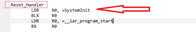
Once the processor enters Reset_Handler, the very first instructions you will find in the IAR startup file are:
LDR  R0, =SystemInit
BLX  R0
This simply calls the vendor-provided SystemInit() function, whose job is to bring the hardware into a safe and predictable state before the C runtime starts executing.
What SystemInit() usually handles:
- SystemInit performs all the essential low-level configuration, including:
- Setting up the system clock (PLL, prescalers, clock sources)
- Configuring Flash wait states for higher clock speeds
- Enabling the FPU (if present)
- Initializing caches, MPU, and bus-related settings
- Updating the VTOR register if the vector table has been moved from the default address
These steps ensure that the core is running on stable hardware foundations.
Stage 3: Jump to IAR Runtime Entry Point
Once the basic hardware setup is complete, the startup code transfers control to the IAR C/C++ runtime. In the startup file, this is done with:
LDR R0, =__iar_program_start
BX R0
These instructions transfer control from the low-level assembly code to the IAR Runtime Library, which is responsible for initializing the entire C/C++ runtime environment.
System state at this point:
- Hardware is now stable
- System clocks are configured
- The FPU (if available) is enabled
- Memory sections (.data, .bss, static objects) are not yet initialized
In other words, assembly-level setup is done, and this is the moment when IAR’s runtime takes over and prepares the memory and environment needed for your application.
Stage 4: C/C++ Runtime Initialization
Once execution enters __iar_program_start, the IAR runtime begins setting up the full C/C++ environment. This stage prepares memory, global variables, and C++ objects before main() can run.
1. Floating-Point Unit Initialization:
The runtime first calls:
__iar_init_vfp()
This configures the Floating-Point Unit (FPU), including its registers, stacking mode, and lazy context-saving behavior.
2. Optional Low-Level Initialization:
Before the standard C/C++ runtime performs memory setup, the IAR startup sequence calls an optional user function:
// Called by the IAR runtime:

int __low_level_init(void);
The Role of __low_level_init():
- Custom Control: This function is a critical hook for developers who need to perform early configuration that might influence the memory setup.
- The Gatekeeper: Its primary function is to act as a gatekeeper for the time-consuming memory initialization steps (copying .data and clearing .bss.
- If this function returns 0, all data initialization is skipped.
- This is especially useful for bootloaders, RAM-only execution, or scenarios where you want full control over memory setup.
3. Data Initialization:
Memory initialization is performed through:
__iar_data_init3()
It handles two crucial tasks:
1. Zero-initializing the .bss section
All uninitialized global and static variables (in .bss) are set to zero.
2. Copying .data from Flash → RAM
Variables with initial values stored in Flash are copied into their RAM locations so the program can modify them.
4. C++ Runtime Initialization:
Finally, IAR calls the C++ initialization wrapper:
__cmain()
This function:
- Invokes all global and static C++ constructors
- Prepares the runtime state required before entering main()
This ensures every global object is fully constructed and ready for use.
Stage 5: Entering main() — Your Application Finally Starts:
After the hardware is set up and the memory is prepared, the last step in the startup process is to call your program’s starting point:
main();
This is where your actual application code finally begins to run.
At this moment:
- System clock = configured
- FPU = enabled
- RAM = initialized (.data/.bss ready)
- Global/static constructors = executed
- Vector table = active
- Interrupts = safe to use
You now have complete control.
Structure of the ARM Cortex-M4 Startup File:
Let’s walk through this Startup file’s structure.
1. Vector Table Declaration:
This array of function pointers defines where the MCU should jump for each interrupt. The first entry is the initial stack pointer, and the second is the Reset_Handler.
    EXPORT  __vector_table
    EXPORT  Reset_Handler

    AREA    RESET, DATA, READONLY
    ALIGN

__vector_table
    DCD     __initial_sp
    DCD     Reset_Handler
    DCD     NMI_Handler
    DCD     HardFault_Handler
    ; ... (rest of the interrupt vectors)
Note: IAR places the vector table in flash at address 0x08000000 unless changed via linker.
2. Stack and Heap Configuration:
The actual stack size is defined in the IAR linker configuration file (.icf), not directly in the startup assembly file. The startup file declares symbols for the initial stack pointer, often like this:
EXTERN __initial_sp
3. Default Exception and Interrupt Handlers:
All exception and IRQ handlers are declared as weak by default. If you do not provide your own implementations, they will default to a dummy handler that runs an infinite loop. You can override any of these handlers simply by defining a function with the same name in your C code.
NMI_Handler
        B       .

HardFault_Handler
        B       .
4. The Reset Handler:
This is the first function called after a reset. In IAR, the Reset Handler typically looks like:
Reset_Handler:
        LDR     R0, =SystemInit
        BLX     R0

        LDR     R0, =__iar_program_start
        BX      R0
Here, __iar_program_start is an internal C library function provided by provided by the IAR runtime library. It’s called by the Reset_Handler in the startup file.
SystemInit()is a function defined in system_stm32h5xx.c. It typically sets up:- Clock configuration
- PLL setup
- FPU configuration
- Possibly watchdog disabling, etc.
__iar_program_start()is the IAR-specific C runtime entry point:- Zero-initialization of .bss
- Copying initialized .data from flash to RAM
- Calling global/static C++ constructors
- Calling main()
📝 Note: If you don’t see SystemInit being called explicitly, then you should add it yourself just before __iar_program_start.
⚙️ Customizing the Startup File in IAR:
You code stuck before main()? Here’s what to check:
- Verify the vector table.
Make sure SCB->VTOR points to the correct base address and the table is properly aligned. - Check the stack pointer.
The first word in the vector table must contain a valid initial SP value—usually the top of SRAM. - Review SystemInit().
Look for any incorrect clock or peripheral configurations that could cause a lock-up. - Initialize .data and .bss sections properly.
If the runtime doesn’t zero or copy them correctly, uninitialized variables can cause undefined behavior.
✅ Use IAR C-SPY to debug early startup code.
Place breakpoints in Reset_Handler and step through line-by-line to find where the system fails.
FAQ Related to MCU Startup Code:
1. What is MCU startup code?
MCU startup code is the first set of instructions that run immediately after a microcontroller resets. It initializes the stack pointer, system clock, memory, and runtime environment before calling the main() function.
2. Why is startup code important in microcontrollers?
Startup code prepares the hardware and memory for safe execution. Without it, global variables, system clocks, and essential CPU states would not be initialized correctly.
3. What happens before main() runs on an ARM Cortex-M MCU?
Steps include vector table fetch, SystemInit execution, C/C++ runtime initialization, copying .data variables, zeroing .bss, and finally calling main().
4. Is the startup code different for each compiler?
Yes. IAR, Keil, and GCC all generate slightly different startup files, especially in how they initialize memory and reset handlers.
5. Where is the startup code stored in an MCU?
The startup code is typically stored in Flash memory at the start of the program image, where the vector table resides.
6. Can I modify the startup code in STM32 or ARM Cortex-M?
Yes. You can customize clock setup, memory initialization, or boot behavior by editing the startup assembly file or SystemInit().
7. What is the vector table in MCU startup?
The vector table is a list of addresses that tell the CPU where to find interrupt handlers and the reset handler.
📘 Related Articles:
- Understand the IAR Linker Script for STM32.
- STM32 RCC Reset Domains: System, Power & Backup Explained.
- STM32 Clock Configuration Guide: Understanding the Clock System Step-by-Step.
- How to Calculate Memory Regions in Embedded Systems (Start, End, Size)
- Why Flash Memory is Divided into Banks: A Deep Dive.