We can program 16*2 alphanumeric LCD in two modes 8-bit mode and 4 bit mode. In the previous article, I have already discussed the LCD and its pin configuration. See this link to know the LCD and its 8-bit mode programming.
In this article, I will discuss the steps to display the message on 16*2 alphanumeric LCD using the 4 bits.
We already know that microcontroller has a fixed number of GPIO pins, using the LCD 4-bit we can save the extra pins of the microcontroller.
Note: In LCD 4-bit data write only on the upper nibble of the data bus, means that only D4, D5, D6, and D7 data bus are useful.
Connection of LCD in 4-bit mode
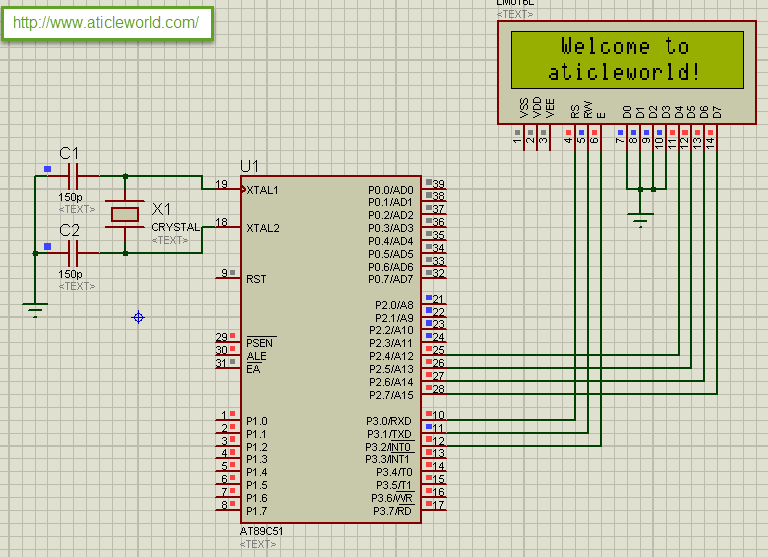
In 4-bit mode, the only upper nibble of the data bus is used for the reading and writing. So D4, D5, D6, and D7 will only attach with GPIO of the microcontroller for reading and writing. In below Image LCD data pins attached with PORT 2. Other connection of LCD 4-bit is the same as in 8-bit mode.

Steps to display a message on LCD using the 4 bits mode
- Initialize the LCD in 4-bit and select the command or data resistor as per your requirement.
- Mask the upper nibble and send to the upper nibble of the LCD data bus.
- Send low to high signal on Enable pin.
- Mask the lower nibble and send to the upper nibble of the LCD data bus.
- Send low to high signal on Enable Pin.
If you want to learn more about the c language, here 10 Free days (up to 200 minutes) C video course for you.
Your free trial is waiting
Example
Suppose you want to send the 0x02 command on LCD, then you have to take the following steps.
Command = 0x02;

Mask the upper nibble.

Command &= 0xF0; /*Mask the upper nible*/

Send the masked command on LCD port.

LCD = Command /* Send upper nible of data*/

Send Enable signal.

Mask the lower nibble.

Command &= 0x0F; /*Mask the lower nible*/

Send the masked command on LCD port

LCD = Command << 4; /*send lower nible of data*/

Send Enable signal.
Simple Program to display a message on LCD using the 4-bit mode
#include<reg51.h>
#include<string.h>
#define LCD P2 /*Attached Lcd on Port*/

sbit rs =P3^0; /*Configure RS Pin*/
sbit rw=P3^1; /*Configure R/W pin*/
sbit e =P3^2; /*Configure Enable pin*/


/*Function Declaration*/
void LcdCommand(const char cCommand);
void DisplayMessage(const char *pszMessage);
void LcdInit(void);
void Delay(unsigned int);


/*Main function*/
int main()
{

    short siLoop = 0;
    const char *pszDisplayMsg1 = "Welcome to";
    const char *pszDisplayMsg2 = "aticleworld!";

    LcdInit();  /*Lcd Initialize*/
    while(1)
    {

        LcdCommand(0x83); /*Address of DDRAM*/
        DisplayMessage(pszDisplayMsg1);
        LcdCommand(0xc2); /*Address of DDRAM*/
        DisplayMessage(pszDisplayMsg2);
    }
}


/*Function to write command on Lcd*/
void LcdCommand(const char cCommand)
{

    rs = 0;
    rw = 0;
    LCD = (0xF0 & cCommand); /*upper nible of command*/
    e=1;
    Delay(1);
    e=0;
    LCD = cCommand<<4;   /*Lower nible command*/
    e=1;
    Delay(1);
    e=0;

}


/*Function to write display data on Lcd*/
void DisplayMessage(const char *pszMessage)
{

    rs = 1;
    rw = 0;
    while(*pszMessage!='\0')
    {
        LCD = (0xF0 & (*pszMessage));/*upper nible of data*/
        e=1;
        Delay(1);
        e=0;
        LCD = (*pszMessage)<<4; /*Lower nible of data*/
        e=1;
        Delay(1);
        e=0;
        pszMessage++;
    }
}

/*Function to Provide delay*/
void Delay(unsigned int i)
{
    int j,k;
    for(j=0; j<i; j++)
    {
        for(k=0; k<1275; k++);
    }
}

/*Function to Initialize the Lcd*/
void LcdInit(void)
{

    LcdCommand(0x01);
    LcdCommand(0x02);
    LcdCommand(0x28);
    LcdCommand(0x0c);
}
Recommended Post:
- Led blinking program in c for 8051.
- Interfacing of switch and led using the 8051
- Interfacing of Relay with 8051 microcontroller
- Moving message display on LCD using 8051
- LCD 4-bit mode c code for 8051.
- Create LCD custom characters for 16×2 alphanumeric LCD
- Interfacing of keypad with 8051
- Electronic digital lock using the 8051
- Interfacing of EEPROM with 8051 microcontrollers using I2C
- Embedded c interview questions.
- 8051 Microcontroller Pin Diagram and Pin Description.
- Can protocol interview questions.
- 8051 Architecture.
