In this article, we will explore how to interface an EEPROM with an 8051 microcontroller using the I2C protocol. In real-world applications, microcontrollers often come with a limited amount of internal memory. This limitation can become a significant bottleneck during project development, especially when persistent data storage is required.
To overcome this, microcontrollers typically offer the flexibility to connect external memory components. Data can be stored in such external memory devices using communication protocols like I2C, SPI, or others.
Here, I will demonstrate a simple example: storing a single byte of data into an EEPROM and reading it back. To verify the operation, the read byte will be compared with the original written byte. If they match, an LED will toggle, indicating a successful read/write cycle.
What is an EEPROM?
EEPROM stands for Electrically Erasable Programmable Read-Only Memory. It is a type of non-volatile memory, meaning it retains data even when power is removed. Unlike flash memory, which erases data in sectors, EEPROM allows byte-level erasure and writing, though it is generally slower.
Some microcontrollers include a small amount of built-in EEPROM for storing essential data like configuration settings, usernames, or passwords.
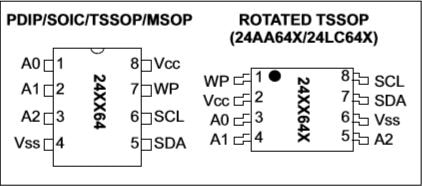
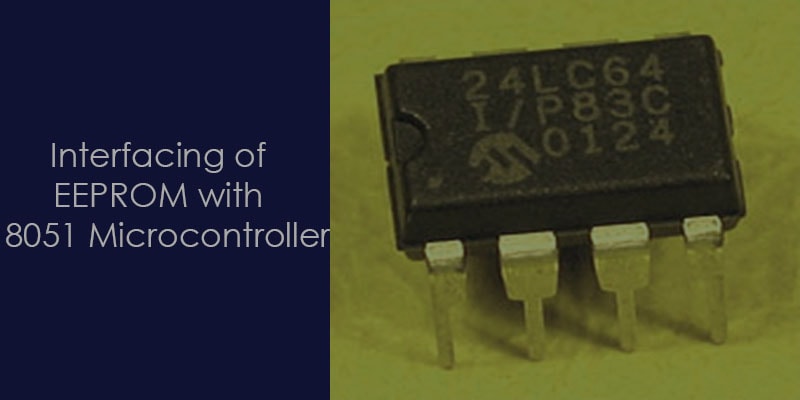
There are various EEPROMs available in the market from different manufacturers. In this article, we will focus on the 24LC64 EEPROM by Microchip Technology. This EEPROM communicates with the microcontroller via the I2C bus, making it easy to interface using just two wires.
✅ Key Features of 24LC64 (EEPROM):
- Memory Organization: 64 Kbit (8 KB) organized into 8 blocks of 8 Kbit each.
- Interface: Two-wire I2C serial interface, supporting both standard (100 kHz) and fast mode (400 kHz).
- Page Write Buffer: Up to 32 bytes per write operation.
- Endurance: Up to 1,000,000 write/erase cycles per memory location.
- Data Retention: Over 200 years at typical operating conditions.
- Operating Voltage Range: 2.5V to 5.5V, making it compatible with a wide range of MCUs.
- Low Power Consumption: Supports standby and low current modes.
- Hardware Write Protection: Selectable via the WP (Write Protect) pin.
Here I have found a very useful Embedded Systems Programming courses for beginners, as well as experienced mobile and desktop software developers by Jeremy Willden.
![]()
Control bytes of 24lc64 (EEPROM):
Before diving into programming the 24LC64 EEPROM, it is important to understand how its control byte works in I2C communication. This byte is sent by the master device immediately after the START condition and plays a crucial role in addressing the EEPROM and defining the operation type.
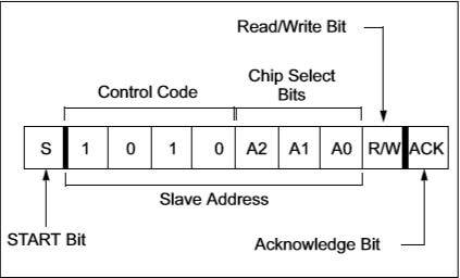
The control byte is an 8-bit value structured as follows:
- Bits 7–4 (Control Code): Fixed as 1010 for all EEPROM operations (both read and write).
- Bits 3–1 (Chip Select – A2, A1, A0): These bits correspond to the hardware-configurable address pins of the EEPROM. They allow you to connect up to 8 EEPROM devices (with unique addresses) on the same I2C bus.
- Bit 0 (R/W): This bit indicates the operation type:
- 0 for Write.
- 1 for Read
Example:
If A2, A1, and A0 are all tied to ground (logic 0), the control byte for:
- Write operation: 10100000 (0xA0)
- Read operation: 10100001 (0xA1)
📘 Basic Requirements for Interfacing EEPROM with 8051 Microcontroller
Interfacing an EEPROM like the 24LC64 with an 8051 microcontroller requires a few key components and a basic understanding of how the I2C protocol works
1️⃣ Knowledge of the I2C Protocol:
To interface an EEPROM with any microcontroller, it’s important to understand the I2C (Inter-Integrated Circuit) protocol. I2C is a simple, serial communication protocol used to connect low-speed peripherals to processors and microcontrollers.
📝 Tip: If you’re unfamiliar with I2C, check out our dedicated article on I2C Protocol Basics before proceeding with this tutorial.
2️⃣ 8051 Microcontroller:
In this example, the 8051 microcontroller acts as the I2C master, initiating all communication to perform read and write operations with the EEPROM. Unlike some modern microcontrollers (like PIC or STM32), the 8051 (At89s52) does not have built-in I2C hardware, so we implement I2C communication using bit-banging.
3️⃣ EEPROM (24LC64):
The 24LC64 EEPROM is used to store permanent data like usernames and passwords. It offers 64Kbits (8KB) of storage, organized as 8 blocks of 8Kbits each. The memory locations range from address 0x0000 to 0x1FFF (8191 in decimal), with each location capable of storing 1 byte (8 bits).
For example: Writing ‘A’ to address 0x0001, reading from 0x0001 will return ‘A’.
🔍 To store data larger than one byte, you will need to use multiple memory locations (cells).
🔌 Interfacing 24LC64 EEPROM with 8051 Using I2C (Bit-Banging):
As you may know, the AT89S52 lacks dedicated I2C hardware, so we simulate the I2C protocol using GPIO pins for the SDA and SCL lines. It’s important to strictly follow the I2C protocol rules:
- Master initiates and terminates communication.
- Data changes only when the clock (SCL) is LOW.
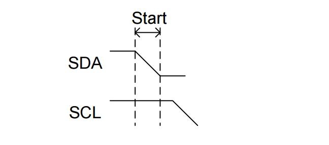
⚠️ Exceptions to the rule:- Start Condition: SDA transitions from high to low while SCL is high.
- Stop Condition: SDA transitions from low to high while SCL is high.
- Repeated Start Condition: Another Start issued without a Stop.
START CONDITION:
A Start Condition occurs when the SDA line transitions from HIGH to LOW while the SCL line remains HIGH. It is used by the master to signal the beginning of communication on the bus.
void StartI2c(void)
{

    SDA_BUS  = 1;
    SCL_BUS  = 1;
    delay(I2C_DELAY);
    SDA_BUS  = 0;
    delay(I2C_DELAY);
}
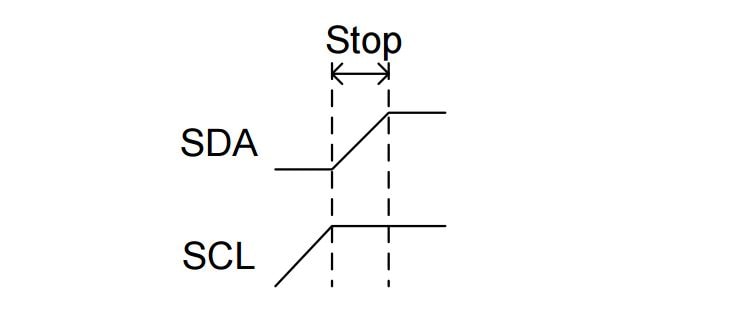
STOP CONDITION:
A STOP condition occurs when the SDA line transitions from LOW to HIGH while the SCL line remains HIGH. This specific pattern is recognized by all devices on the bus as the end of the current transaction.
void StopI2c(void)
{

    SCL_BUS  = 0;
    delay(I2C_DELAY/2);
    SDA_BUS  = 0;
    delay(I2C_DELAY/2);
    SCL_BUS  = 1;
    delay(I2C_DELAY/2);
    SDA_BUS  = 1;
    delay(I2C_DELAY);

}
REPEATED START:
During the communication it the master does not want to release the bus then it just asserts a repeated start condition to continue the other communication. In below example controller first write a single byte to the EEPROM after that it just asserts a repeated condition to change the mode from the write to read.
void RepeatedStartI2c()
{

    SCL_BUS  = 0;
    delay(I2C_DELAY/2);
    SDA_BUS  = 1;
    delay(I2C_DELAY/2);
    SCL_BUS  = 1;
    delay(I2C_DELAY/2);
    SDA_BUS  = 0;
    delay(I2C_DELAY);

}
WRITE-BYTE TO THE EEPROM
A master first asserts the start bit on I2C bus and after the start bit, send the control byte to the EEPROM followed by the write bit (0) and check the acknowledgment bit.
If the master does not get the acknowledgment from the EEPROM then it will continuously send the control byte to the EEPROM and poll the acknowledgment bit.
When the master gets the acknowledgment then it sends the address of the cell (A15 to A0) where it wants to store the byte. In the last of the communication when the master wants to stop the communication it asserts a stop condition.
void write_byte_to_eeprom(unsigned int addr,unsigned char byte)
{

    StartI2c();

    while(write_i2c(device_addr+0)==1)
    {
        StartI2c();
    }

    write_i2c(addr>>8);
    write_i2c((unsigned char)addr);
    write_i2c(byte);
    StopI2c();

}
READ BYTES FROM THE EEPROM
A master first asserts the start bit on I2C bus and after the start bit, send the control byte to the EEPROM followed by the read bit (1) and check the acknowledgment bit.
If the master does not get the acknowledgment from the EEPROM then it will continuously send the control byte to the EEPROM and poll the acknowledgment bit.
When the master gets the acknowledgment then it sends the address of the cell (A15 to A0) where it wants to read the byte. After sending the address of cell master sends the repeated start condition on the I2C bus to read the byte from the address which had sent by the master.
unsigned char read_byte_from_eeprom(unsigned int addr)
{

    unsigned char rxdata =0;
    StartI2c();
    while(write_i2c(device_addr+0)==1)
    {
        StartI2c();
    }
    write_i2c(addr>>8);
    write_i2c((unsigned char)addr);
    RepeatedStartI2c();
    write_i2c(device_addr+1);
    rxdata=read_i2c();
    SendNackBit();
    StopI2c() ;

    return rxdata;

}
PROGRAM TO WRITE AND READ THE BYTE FROM THE EEPROM
The below code explains interfacing EEPROM with 8051 micro-controller using the I2C protocol. In this program, we store a single byte in EEPROM through the I2C protocol and after that read back this written byte from the EEPROM.
In this program for the verification, I will toggle the LED if the read byte is intact.
#include <reg51.h>


//Delay for I2c
#define I2C_DELAY    50

//Define Led Toggle Time
#define TOGGLE_LED  20000

//control address of 24lc64
#define device_addr 0xA0

#define ACK_BIT    0


//Define the Pin for the I2c and lec
sbit SDA_BUS = P2^0;
sbit SCL_BUS = P2^1;
sbit Led = P3^0;


/*=========================================
   Prototypes for I2c functions
 ==========================================*/


void InitI2c(void);

void StartI2c(void);

void RepeatedStartI2c(void);

void StopI2c(void);

void SendAckBit(void);

void SendNackBit(void);

void delay(unsigned int);

bit write_i2c(unsigned char);

unsigned char read_i2c(void);

void write_byte_to_eeprom(unsigned int,unsigned char);

unsigned char  read_byte_from_eeprom(unsigned int);


/*=========================================
   Definition of I2c functions
 ==========================================*/


/**
\brief of  delay function.

This function provide the delay which is used in clock generation.
*/
void delay(unsigned int d)
{
    unsigned int i;

    for(i=0; i<d; i++);

}


/**
\brief of InitI2c function.
This function  use to make the data line and clock line idle to put the both line high

*/
void InitI2c(void)
{
    SDA_BUS =1;
    SCL_BUS =1;
}


/**
\brief of StartI2c function.
This function performs the start operation to initiate the communication.

*/
void StartI2c(void)
{
    SDA_BUS  = 1;
    SCL_BUS  = 1;
    delay(I2C_DELAY);
    SDA_BUS  = 0;
    delay(I2C_DELAY);
}


/**
\brief of void RepeatedStartI2c function.

When master does not want to relaese the control from the bus then it assert the repeated
start condition on the i2c bus.
*/
void RepeatedStartI2c()
{
    SCL_BUS  = 0;
    delay(I2C_DELAY/2);
    SDA_BUS  = 1;
    delay(I2C_DELAY/2);
    SCL_BUS  = 1;
    delay(I2C_DELAY/2);
    SDA_BUS  = 0;
    delay(I2C_DELAY);
}


/**
\brief of void StopI2c function.

When master want to stop the communication then it will assert the stop condition to the i2c bus.
*/
void StopI2c(void)
{
    SCL_BUS  = 0;
    delay(I2C_DELAY/2);
    SDA_BUS  = 0;
    delay(I2C_DELAY/2);
    SCL_BUS  = 1;
    delay(I2C_DELAY/2);
    SDA_BUS  = 1;
    delay(I2C_DELAY);
}


/**
\brief of  SendAckBit function.

This function use to send the acknoledgement(ACK) bit the i2c bus.
*/
void SendAckBit()
{
    SCL_BUS  = 0;
    delay(I2C_DELAY/2);
    SDA_BUS  = 0;
    delay(I2C_DELAY/2);
    SCL_BUS  = 1;
    delay(I2C_DELAY);

}


/**
\brief of  SendNackBit function.

This function use to send the Non-acknoledgement(NACK) bit the i2c bus.
*/
void SendNackBit(void)
{
    SCL_BUS  = 0;
    delay(I2C_DELAY/2);
    SDA_BUS  = 1;
    delay(I2C_DELAY/2);
    SCL_BUS  = 1;
    delay(I2C_DELAY);
}


/**
\brief of write_i2c function.

This function use to send signle byte to the I2C Data Bus
*/
bit write_i2c(unsigned char byte)
{
    unsigned char i;
    for(i=0; i<8; i++)
    {
        SCL_BUS  = 0;
        delay(I2C_DELAY);
        if((byte<<i)&0x80)
            SDA_BUS  = 1;
        else
            SDA_BUS  = 0;
        delay(I2C_DELAY/2);

        SCL_BUS  = 1;
        delay(I2C_DELAY);
    }
//ack from slave //
    SCL_BUS  = 0;
    SDA_BUS  = 0;
    delay(I2C_DELAY/2);
    SCL_BUS  = 1;
    delay(I2C_DELAY);
    return SDA_BUS;
}


/**
\brief of write_i2c function.

This function use to read the data from the I2C data bus
*/
unsigned char read_i2c(void)
{
    unsigned char i,d, rxdata=0;
    for(i=0; i<8; i++)
    {

        SCL_BUS  = 0;
        SDA_BUS  = 1;
        delay(I2C_DELAY);
        SCL_BUS  = 1;
        delay(I2C_DELAY/2);
        d=SDA_BUS;
        rxdata=rxdata|(d<<7-i);
        delay(I2C_DELAY);
    }
    return rxdata;

}


/**

\brief of write_byte_to_eeprom function.

This function use to single byte the eeprom at desire address
*///Write Data to eeprom memory
void write_byte_to_eeprom(unsigned int addr,unsigned char byte)
{
    StartI2c();
    while(write_i2c(device_addr|0)==1)
    {
        StartI2c();
    }
    write_i2c(addr>>8);
    write_i2c((unsigned char)addr);
    write_i2c(byte);
    StopI2c();
}


/**
\brief of read_byte_from_eeprom function.

This function use to read the data byte from eeprom at the desire the address
*/
unsigned char read_byte_from_eeprom(unsigned int addr)
{
    unsigned char rxdata =0;
    StartI2c();
    while(write_i2c(device_addr|0)==1)
    {
        StartI2c();
    }
    write_i2c(addr>>8);
    write_i2c((unsigned char)addr);
    RepeatedStartI2c();
    write_i2c(device_addr|1);
    rxdata=read_i2c();
    SendNackBit();
    StopI2c() ;

    return rxdata;
}


// Main function

void main(void)
{
    unsigned char rxbyte=0;
    unsigned char cSendByte = 'a';

    Led  = 0;
    SDA_BUS = 0;
    SCL_BUS = 0;

    InitI2c();
    write_byte_to_eeprom(0x0001,cSendByte);
    rxbyte=read_byte_from_eeprom(0x0001);


    while(1)
    {

        if(rxbyte ==  cSendByte)
        {
            Led =1;		   // Led Off
            delay(TOGGLE_LED);
            Led =0;			  // Led on
            delay(TOGGLE_LED);

        }
    }
}
Recommended Post:
- I2C interview Questions.
- SPI vs I2C
- Led blinking program in c for 8051.
- Interfacing of switch and led using the 8051
- Interfacing of Relay with 8051 microcontroller
- Moving message display on LCD using 8051
- LCD 4-bit mode c code for 8051.
- Create LCD custom characters for 16×2 alphanumeric LCD
- Interfacing of keypad with 8051
- Electronic digital lock using the 8051
- Interfacing of EEPROM with 8051 microcontrollers using I2C
- Embedded c interview questions.
- 8051 Microcontroller Pin Diagram and Pin Description.
- Can protocol interview questions.
- 8051 Architecture.