In this article, I will discuss the Fundamentals of UART Communication. I plan to create a series of articles on UART/USART and implement the source code for different microcontrollers, e.g., 8051, PIC, STM32, AVR, and Arduino.
So, let’s start this article with an understanding of UART…
What is UART/USART?
In embedded systems, efficient data communication between devices is essential. Two commonly used serial communication interfaces for this purpose are UART/USART.
UART and USART are hardware communication protocols used for serial data transmission in embedded systems. They enable devices like microcontrollers and sensors to exchange data efficiently.
Let’s see UART and USART.
UART:
UART (Universal Asynchronous Receiver/Transmitter) is one of the most widely used serial communication protocols, particularly in embedded systems. It is a hardware communication peripheral that allows asynchronous data exchange between two devices without needing a shared clock signal.
The baud rate defines the speed of data transmission between devices. Both devices must be configured with the same baud rate for reliable communication. UARTs often include a fractional baud rate generator, allowing precise control over various baud rates and supporting a wide range of communication speeds.
Unlike synchronous protocols like SPI or I2C, UART transmits data bit by bit using only two lines. That means UART mainly relies on two wires: one for transmitting (TX) and one for receiving (RX), along with a shared ground connection.
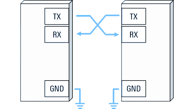
UART defines a set of rules for this exchange, making it simple and reliable for device-to-device communication. It is the reason, UART is ideal for long-distance, low-speed, point-to-point communication, such as:
- Microcontroller-to-GPS modules.
- Debug consoles.
- PC-to-MCU via USB-to-Serial adapters.
USART:
USART supports both asynchronous communication (like UART) and synchronous communication, which uses a shared clock. It also handles protocols such as LIN (Local Interconnect Network), smartcard protocols, and IrDA (Infrared Data Association). These enhancements make USART suitable for more complex embedded applications.
For more advanced systems, USART (Universal Synchronous-Asynchronous Receiver/Transmitter) builds on UART’s features.
Both UART and USART support three modes of communication:
- Simplex (data flows in one direction only),
- Half-duplex (data flows in both directions, but only one side can transmit at a time),
- Full-duplex (both sides can transmit and receive data simultaneously).
In UART/USART devices, data is exchanged in the form of frames. Each frame contains bits sent sequentially, and the receiving device reassembles them into complete bytes. Will see it in detail in the section below of this article.
STRUCTURED BREAK-DOWN OF UART FRAME:
In UART communication, data is transmitted in frames. Each UART frame consists of several structured components that ensure proper synchronization and error detection between the transmitter and receiver.
The bits within the UART frame are transmitted using the Non-Return-to-Zero (NRZ) format. In NRZ, each bit is represented by a constant voltage level. Let’s see what is meaning of the NRZ standard format.
NRZ Standard Format:
The UART/USART provides a configurable interface for full-duplex communication with external devices using the industry-standard NRZ asynchronous serial protocol.
Where, NRZ is a digital line encoding scheme where:
- Binary 1 and 0 are represented using two distinct, constant voltage levels.
- The signal does not return to a neutral or zero voltage level between bits.
- It is commonly used in digital communication systems such as USART, USB, hard drives, Ethernet, and more due to its simplicity and efficiency in signal transmission.
Let’s take a closer look at the components that make up each UART frame:
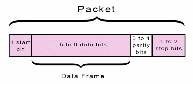
UART frame format:
A typical UART frame consists of data bits placed between a start bit and one or more stop bits, with an optional parity bit for error checking
Let’s understand the different parts of the communication frame of UART/USART.
Start Bit:
Data transmission begins with the start bit. UART data transmission line is normally held at a high voltage level when idle (it’s not transmitting data).
To start the transmission of data, the transmitting UART pulls the transmission line from high to low for one lock cycle. When the receiving UART detects the high-to-low voltage transition, it begins reading the bits in the data frame at the frequency of the baud rate.

Data Bits (Data Frame):
The data frame contains the actual data being transferred. It can be configurable to 5, 6, 7, 8, or 9 bits per frame, depending on the system’s settings. It also supports the programmable data order with MSB-first or LSB-first shifting but in most cases, the data is sent with the least significant bit first.
Parity:
Parity describes the evenness or oddness of a number. It is an error-checking method that adds an extra bit, called the parity bit, to the data. The parity bit helps verify the integrity of the transmitted information.
This method helps us to find out the errors introduced by electromagnetic interference, mismatched baud rates, or long-distance communication. But this method also has some limitations which will be discussed in the separate blog post.
Now let’s understand how the parity mechanism works:
Enable parity:
First, you need to enable the parity setting even parity or odd parity.
Now parity works according to the parity setting, even or odd.
Setting the Parity Bit:
Before sending a data frame, the transmitting UART calculates the parity bit based on the “1” bits in the data.
- For even parity, the UART sets the parity bit to
0if the total number of “1” bits is even. Otherwise, it sets the parity bit to1make the total even. - For odd parity, the UART sets the parity bit to
0if the total number of “1” bits is odd. Otherwise, it sets the parity bit to1make the total odd.
Receiving and Verifying:
- After reading the data frame, the receiving UART counts the “1” bits in the data and includes the parity bit in its calculation.
- It compares the total against the expected parity (even or odd) based on the parity configuration.
If the parity check fails, the corresponding flag is set, and an interrupt is generated if the interrupt is available and enabled.
Let’s see an example for a better understanding.
Example: If the transmitted data is 01010101 (4 “1” bits):
- Even Parity: The UART sets the parity bit to 0.
- Odd Parity: The UART sets the parity bit to 1.
Stop Bit:
The stop bit denotes the end of the data transmission. The sending UART drives the data transmission line from a low voltage to a high voltage for 0.5, 1, 1.5, or 2-bit (s) duration. It is configurable and depends on the requirement.
8N1 UART configuration:
A typical 8N1 UART configuration refers to a common serial communication frame format and consists of:
- 8: Data bits – each frame contains 8 bits of actual data.
- N: No parity bit – there is no parity error-checking.
- 1: One stop bit – the frame ends with a single stop bit.
| Start Bit | 8 Data Bits | No Parity | 1 Stop Bit |
Bit Count:
- Start bit: 1 bit (always low)
- Data bits: 8 bits
- Parity: 0 bits
- Stop bit: 1 bit (always high)
So each frame consists of 10 bits total.
USART Main Features:
Here are the following main features of USART. For more details, you can check your MCU data sheet.
Modes of Operation:
- Asynchronous Mode:
Data is transmitted without a shared clock. This is commonly used in protocols like RS-232, RS-485, or TTL-level serial communication. - Synchronous Mode:
Data is transmitted along with a shared clock. While USART can support synchronous mode, SPI is technically a different peripheral, although similar in function.
Baud Rate:
- Configurable transmission speed, typically ranging from 300 baud to several Mbps, depending on hardware. Common values are: 9600, 115200, etc.
Data Frame Structure:
- Start Bit: Indicates the start of transmission (logic low).
- Data Bits: Typically 8 bits (configurable from 5 to 9 bits depending on the hardware).
- Parity Bit (optional): Can be even, odd, or none, used for error checking.
- Stop Bit(s): Usually 1 or 2 bits to mark end of a frame.
Communication Mode:
- Full-Duplex:
Simultaneous transmission and reception on separate lines (TX and RX). - Half-Duplex (optional):
In some configurations (e.g., RS-485), transmission and reception share the same line, so data flows in only one direction at a time.
Error Detection:
- Parity Error: When the parity of received bits doesn’t match the expected.
- Framing Error: When the stop bit is missing or incorrect.
- Overrun Error: When the receive buffer is full before the previous data is read.
Flow Control:
- Hardware Flow Control:
RTS (Request to Send) / CTS (Clear to Send) lines to prevent data overflow. - Software Flow Control:
Uses control characters like XON/XOFF to pause/resume data transmission.
Note: When FIFO mode is enabled, RTS is asserted only when RXFIFO is full.
Interrupts:
USART can trigger interrupts on:
- Receive complete
- Transmit complete
- Transmit data register empty
- Error events (parity, overrun, etc.)
Configurable Pin Mapping:
Alternate Function I/O allows USART signals (TX, RX, CTS, RTS, CLK) to be routed to different microcontroller pins.
Protocol Support:
- Asynchronous Mode: Supports RS-232, RS-485, and TTL-level serial protocols.
- Synchronous Mode: Allows synchronous data transmission (not a replacement for SPI, but sometimes similar).
Multi-Processor Communication:
Allows communication with multiple devices using address-based data handling and mute mode.
USART FIFOs and thresholds:
Most modern microcontrollers (like STM32) include a FIFO buffer inside the UART hardware. It allows temporary storage of multiple bytes for TX and RX.
Data Transmission and Reception in UART
In UART communication, data is transmitted serially — bit by bit — and it is essential for both the transmitter and receiver to agree on settings like baud rate, parity, and stop bits to ensure successful communication.
Let’s see the steps involved in data transmission and reception.
📝 Steps of UART Transmission:
When no data is being transmitted, the UART TX line remains idle, represented by a logic HIGH level.
- TTL (Transistor-Transistor Logic): +3.3V or +5V, depending on the system.
- RS-232: −3V to −15V (inverted logic)
In this state, both the transmitter and receiver are idle but ready, waiting for data to be sent or received.
Now, let’s understand the basic sequence of data transmission and reception in UART (or USART):
Step 1- Data Reception by Transmitting UART
The transmitter can send data words of either 7 or 8, or 9 bits, depending on the configuration. The transmitting UART receives a parallel byte of data (typically 8 bits) from the system data bus (e.g., from a microcontroller, processor, or memory). This parallel data is temporarily stored in the transmit data register.
![]()
Step 2- Framing the Data Frame:
The UART then prepares the data for serial transmission by framing it as per the configured protocol (e.g., 8N1). This frame typically consists of:
- Start Bit: Mark the beginning of transmission.
- Data Bits: Usually 8 bits of payload data, transmitted LSB first.
- Parity Bit (optional): Used for error detection.
- Stop Bit(s): Marks the end of the data frame (one or more).
Step 3- Serial Data Transmission:
The complete frame (start bit, data bits, parity bit, and stop bits) is transmitted serially bit by bit over the TX line using a shift register. The baud rate (e.g., 9600, 115200) controls the speed of bit transmission, with both devices needing to share the same baud rate for accurate communication.
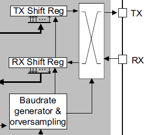
Every character is preceded by a start bit, which corresponds to a low logic level for one bit period. The character is terminated by a configurable number of stop bits.
📝 Steps of UART Reception:
Before data reception begins, the UART Rx line remains idle at a logic HIGH level. The USART can receive data words of either 7 or 8, or 9 bits, depending on the configuration.
Step 1 – Idle Monitoring:
- The receiving UART continuously monitors the RX line.
- In the idle state, the RX line remains at a logic HIGH level (e.g., 3.3V or 5V in TTL logic, or −3V to −15V in RS-232).
- The UART waits for a falling edge, which indicates the start of a new frame.
Step 2- Start bit detection:
- When a falling edge is detected on the RX line, it is interpreted as a start bit (logic LOW).
- After detecting the start bit, the UART starts sampling subsequent bits at calculated intervals based on the oversampling setting.
In UART, oversampling means sampling each bit multiple times per bit period to more accurately determine the bit’s logic level. The start bit detection sequence is the same when oversampling by 16 or by 8.
📌16 oversampling means that for each bit period, the UART samples the RX line 16 times using an internal clock that runs 16 times faster than the baud rate.
Example,
Let’s say your UART is configured for a baud rate of 9600 bps.
In 16x oversampling, the UART’s internal sampling clock runs at:
9600 × 16 = 153,600 samples/second
Each bit is therefore divided into 16 time slots, and the receiver samples the RX line once every 1/16th of the bit time.
Step 3: Character reception:
- During a USART reception, data is shifted out least significant bit first (default configuration) through the RX pin.
- The UART samples the RX line in the middle of each bit period, ensuring accurate bit detection.
- Accurate timing is maintained by dividing each bit period into multiple internal clock cycles (16 or 8), depending on the oversampling mode.
Optional Parity Bit Check:
- If parity checking is enabled, the next received bit is considered the parity bit.
- The UART calculates and compares parity (even or odd) for error detection.
- A mismatch raises a parity error flag.
Step 5 – Stop Bit Validation:
- The UART expects a logic HIGH during the stop bit(s).
- This confirms the end of the frame.
- If the stop bit is not high, a framing error occurs, often due to baud mismatch or noise.
Step 6 – Data Ready for Host:
Once the frame is verified:
- The received bits are converted back to parallel format using a shift register and then sent to the data bus at the receiving end for further processing.
- After this, the byte is transferred to the Receive Data Register (RDR).
- The UART then sets a receive flag or triggers an interrupt to indicate that data is ready
- The UART sets a receive flag or triggers an interrupt to signal that data is ready.
- The host processor can now read the received byte for further processing.
Example:
Suppose we want to send the capital letter “P” using UART communication in the 7-bit ASCII format. The character “P” is represented by the binary value 1010000 (or 0x50 in hexadecimal).
Below is the UART configuration:
- Word Length: 8 bits
- Parity Bit: None
- Data Order: LSB-first
- Stop Bits: One
Now, the following process is done by the transmitting and receiving UART.
- The original Bit order of the ASCII binary value for “P” is 1010000. This is the standard representation, with the most significant bit (MSB) on the left.
- Since the UART is configured for LSB-first, the bit order of “P” is reversed before transmission.
Original Order: 1010000
Reversed Order (LSB First): 0 0 0 0 1 0 1 - UART frames the Data before the transmission and adds framing bits:
- A start bit (logic 0) at the beginning to signal the start of the transmission.
- The 7 data bits in LSB-first order: 0 0 0 0 1 0 1.
- An optional parity bit (not used in this example).
- A stop bit (logic 1) at the end to signal the end of the frame.
- The UART transmits the bits in the following sequence:Start bit (0) → 0 0 0 0 1 0 1 (data bits in LSB-first order) → Stop bit (1).
- After the stop bit, the communication line returns to the idle state (logic 1), waiting for the next data frame.
![]()
Flow Control in UART Communication:
Flow control is a method used to prevent data loss during communication by controlling the rate of data transmission between devices. It becomes crucial in high-speed UART interfaces or systems with limited receive buffer capacity, where the receiver may not process incoming data quickly enough
There are two types of flow control used in UART communication:
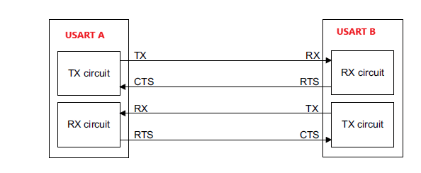
1. Hardware Flow Control (RTS/CTS):
It is possible to control the serial data flow between two devices by using the CTS input and the RTS output.
- RTS (Request to Send): Sent from the receiver to the transmitter to indicate whether it is ready to accept more data.
- CTS (Clear to Send): Sent from the transmitter to the receiver to indicate whether it is ready to transmit data.
The RTS (Request to Send) and CTS (Clear to Send) signals can be used to manage serial data flow between two devices, ensuring that data is transmitted only when the receiving device is ready.
How it works:
- If RTS flow control is enabled, the RTS signal remains deasserted (logic low) while the USART receiver is ready to accept new data. When the receive buffer becomes full, RTS is asserted (logic high), signaling the transmitting device to pause transmission after completing the current frame.
- If CTS flow control is enabled, the transmitter checks the CTS input signal before sending the next frame. If CTS is deasserted (logic low), data transmission proceeds, provided there is data to send. If CTS is asserted (logic high), transmission is paused, and no new data is sent until CTS is deasserted again
2. Software Flow Control (XON/XOFF):
In software flow control, special characters are sent over the data line to control the flow of data:
- XON (Transmit On): This character tells the transmitter to resume data transmission.
- XOFF (Transmit Off): This character tells the transmitter to pause the data transmission.
Unlike hardware flow control, which uses dedicated signal lines, software flow control sends control characters within the data stream itself.
How it works:
- When the receiver’s buffer is full, it sends the XOFF character to the transmitter.
- When the receiver is ready to accept more data, it sends the XON character to resume transmission.
Advantages and Disadvantages of UARTs
Each communication protocol has some pros and cons which means no communication protocol is perfect. But UARTs offer a reliable and straightforward solution for many applications. Here are some advantages and disadvantages of UARTs.
Advantages of UARTs:-
- Simple Wiring: Requires only two wires (Tx and Rx) for data transmission and reception.
- No Clock Signal Needed: Operates asynchronously, eliminating the need for a separate clock signal.
- Error Checking: Includes an optional parity bit for basic error detection.
- Customizable Data Frames: The structure of the data packet (e.g., word length, parity, stop bits) can be configured, provided both sides are set up identically.
- Proven Technology: Widely documented and extensively used in embedded systems and serial communication.
- Hardware flow control: Support the hardware flow control to avoid data loss but hardware flow control is not universally available in all UART modules.
Disadvantages of UARTs:-
- Limited Frame Size: The data frame is restricted to a maximum of 9 bits.
- No Support for Multi-Master or Multi-Slave Systems: UARTs are designed for point-to-point communication and lack built-in support for more complex network topologies.
- Strict Baud Rate Matching: The baud rates of the transmitting and receiving UARTs must be within 10% of each other to ensure reliable communication.