Input and output devices form the foundation of any embedded system. In fact, it is almost impossible to imagine an embedded device without them. Among all I/O devices, the LED and switch are the most fundamental and widely used. LEDs serve as visual indicators (outputs), while switches act as basic input mechanisms.
If you have ever wanted to make an LED respond to a button press just like in real embedded systems, then this tutorial is the perfect place to start.
In this guide, we will learn how to control an LED using a simple SPST (Single Pole Single Throw) switch with the 8051 microcontrollers. You will see how to interface the switch and the LED by connecting the switch to an input pin and the LED to an output pin of the 8051.
I will walk you step-by-step through understanding the circuit connections, the working logic, and finally, writing a C program that includes software debouncing for stable and accurate switch detection.
It may seem simple, but mastering this concept lays the foundation for building reliable and complex embedded systems.
Before diving into the interfacing details, we will take a moment to understand how an LED and a switch actually work. If you are new to these components, don’t worry; we will start from the basics and highlight common mistakes beginners often make, so you can build your first hardware project with confidence.
Understanding LED and Switch:
Before we connect these components to the 8051 microcontrollers, let’s take a closer look at what an LED and a switch actually do and how they behave electrically.
Light Emitting Diode (LED):
An LED (Light Emitting Diode) is a semiconductor device that emits light when current passes through it. It allows current to flow only in one direction from anode (+) to cathode (−) just like a regular diode.
When the LED is forward-biased (anode connected to a higher potential and cathode to a lower potential), electrons and holes recombine in the semiconductor material, releasing energy in the form of visible light. The color of the emitted light depends on the materials and doping used in the LED’s construction.
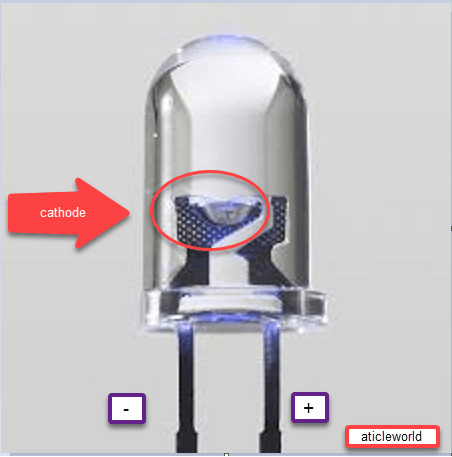
Normally, you can tell the difference between the anode (+) and cathode (−) by looking at the length of the legs:
- Anode (+): Longer leg
- Cathode (−): Shorter leg
But sometimes, both legs are the same length. In that case, look inside the LED:
- The cathode has a larger (broader) metal part inside.
- The anode has a smaller (thinner) metal part.
This trick helps you identify the correct polarity even when the leads are trimmed or equal in size.
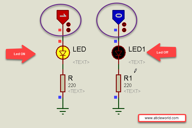
How to Connect an LED:
You should never connect an LED directly to the power supply (for example, to the 5V output of a 7805 regulator). This is because LEDs allow current to flow easily, and if too much current passes through, the LED will get damaged or burn out instantly.
To prevent this, we always connect a resistor in series with the LED. The resistor limits the current and keeps the LED safe.
The value of the resistor depends on how bright you want the LED to glow:
| Brightness Level | Recommended Resistor |
|---|---|
| High Brightness | 100 Ω – 150 Ω |
| Medium Brightness | 220 Ω – 330 Ω |
So, if you just want your LED to glow properly without overheating, use a 330Ω resistor. It is a safe and commonly used value.
Why the Resistor Is Important:
Think of the resistor as a protector for the LED.
When you connect an LED with a resistor, the extra voltage drops across the resistor, keeping only the right amount of voltage for the LED to work safely. Without this protection, too much current will flow, and your LED will burn out in seconds.
A Quick Example,
Let’s say you are using:
- A 5V power supply (like from a 7805 regulator)
- A red LED (which typically drops about 2V)
- You want a current of 10mA (0.01A)
To find the right resistor, use this simple formula:
Resistor (R) = (𝑉𝑠𝑢𝑝𝑝𝑙𝑦 − 𝑉𝐿𝐸𝐷𝐶𝑢𝑟𝑟𝑒𝑛𝑡 ) / I;
Where:
- 𝐼 is the current (in amperes.
- 𝑉 is the voltage (in volts),
- 𝑅 is the resistance (in ohms).
𝑅=(5𝑉−2𝑉)/0.01𝐴 = 300Ω
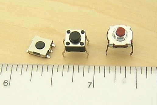
Electrical Switch:
A switch is one of the simplest input devices used in electronics. It allows us to control an output device such as an LED, motor, or relay by sending a signal to the microcontroller or control circuit.
In simple words, a switch opens or closes an electrical circuit, allowing or stopping the flow of current.
- When the circuit is closed, current flows, and the connected output device turns ON.
- When the circuit is open, current stops flowing, and the device turns OFF.
Connection of Electrical Switch:
When we connect a switch to a microcontroller, our goal is to let the microcontroller clearly detect whether the switch is ON (pressed) or OFF (released) — like giving it a clear “yes” or “no” signal.
However, if the switch is not pressed, the input pin connected to it can sometimes become unstable. In this state, the pin doesn’t know whether it should read as HIGH or LOW. This unclear condition is called a floating pin. A floating pin can cause random or unpredictable readings in your program.
To avoid this problem, we use a pull-up or pull-down resistor. These resistors ensure that the input pin always stays at a known logic level (either HIGH or LOW) even when the switch is open.
- A pull-up resistor connects the pin to the supply voltage (Vcc), keeping it HIGH when the switch is open.
- A pull-down resistor connects the pin to ground (GND), keeping it LOW when the switch is open.
Typically, we use resistor values between 4.7kΩ and 10kΩ. These values are strong enough to keep the signal stable while using very little power.
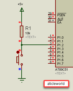
Positive Logic Connection:
In a positive logic connection, we use a pull-down resistor that connects the microcontroller pin to ground (GND).
- When the switch is not pressed, the input pin stays LOW (0) because it’s connected to ground through the pull-down resistor.
- When the switch is pressed, the circuit connects the input pin directly to Vcc, making the signal HIGH (1).
So, in simple terms — pressing the switch gives a HIGH signal and releasing it gives a LOW signal.
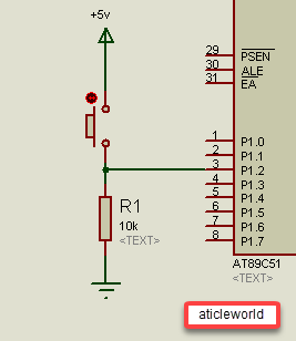
Negative Logic Connection:
In a negative logic connection, we use a pull-up resistor that connects the microcontroller pin to Vcc.
- When the switch is not pressed, the input pin stays HIGH (1) because it’s connected to Vcc through the pull-up resistor.
- When the switch is pressed, the circuit connects the input pin to ground (GND), making the signal LOW (0).
In this setup pressing the switch gives a LOW signal and releasing it gives a HIGH signal.
What Is Switch Bouncing?
When you press or release a mechanical switch, its metal contacts don’t settle immediately. Instead, they quickly touch and separate several times in just a few milliseconds. This creates multiple ON/OFF signals, even though you only pressed the switch once. This effect is called switch bouncing.
If we don’t fix this, the microcontroller might think the switch was pressed many times which can cause bugs or unexpected behavior in your project.
🛠️ How to Fix Switch Bouncing?
There are two common ways to solve this:
1. Hardware Debouncing:
Use extra components like:
- RC circuits (Resistor + Capacitor)
- Debounce ICs (special chips made for this job)
These smooth out the signal before it reaches the microcontroller.
2. Software Debouncing:
Add a short delay in your code (usually 10–20 milliseconds) after detecting a switch press. This gives the signal time to settle before reading it again.
Algorithm to Control LED Using a Switch (SPST)
- Configure the microcontroller pin connected to the LED as an output.
- Configure the microcontroller pin connected to the switch as an input.
- Continuously monitor the status of the switch.
- If the switch is pressed, set the LED pin HIGH (turn the LED ON).
- If the switch is released, turn the LED OFF.
Add a small delay (debounce time) to ensure stable operation and avoid false triggering due to switch bounce.
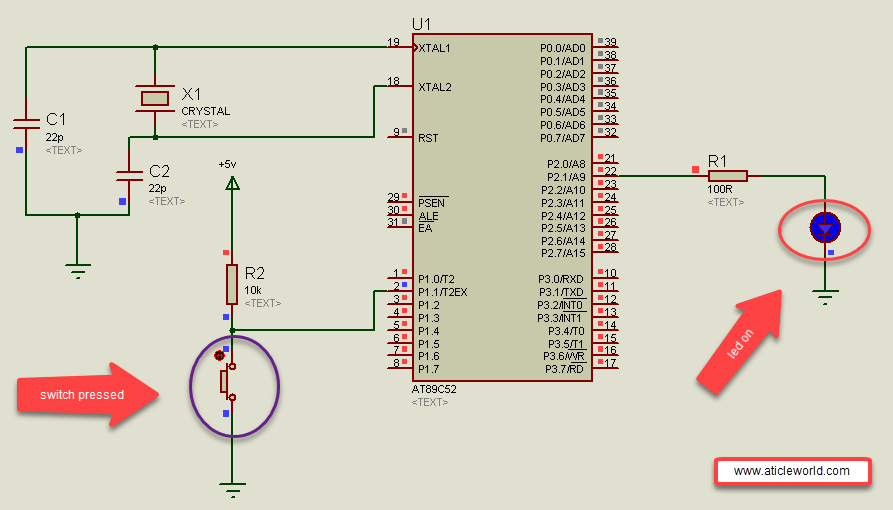
Interfacing LED and Switch with 8051 Microcontroller
In the circuit shown below, an SPST (Single Pole Single Throw) switch is connected to pin P1.1, and an LED is connected to pin P2.1 of the 8051 microcontroller.
Here, we are using a negative logic configuration for the switch connection. In this type of circuit, the input pin reads logic LOW (0) when the switch is pressed, and logic HIGH (1) when the switch is released.
This happens because the switch connects the microcontroller pin to ground (0V) when pressed, while a pull-up resistor keeps it at logic HIGH (5V) when released.
Switch Logic Table:
| Switch State | Pin Voltage | Logic Level | Description |
|---|---|---|---|
| Pressed | 0V | 0 (LOW) | Switch connected to GND |
| Released | 5V | 1 (HIGH) | Pulled up through resistor |
Mode 1: Simple polling approach:
Poll the switch in a loop and toggle the LED when a stable press is detected. This is simple and reliable for low-frequency user buttons. When we write code to control an LED light using a push button switch, we often face switch bouncing issues.
Mechanical switches do not make, or break contact cleanly, instead they generate rapid ON/OFF transitions when pressed or released.
If these bounces are not handled, the microcontroller may detect multiple buttons presses instead of just one.
In this example, I am describing a basic and reliable method to remove switch bouncing issues from your LED control project.
Steps to Remove Switch Bouncing Issues
- Continuously monitor the input pin connected to the push button.
- When the pin state changes, wait for a few milliseconds (the wait time depends on the switch quality and speed).
- Recheck the pin — if the state is still the same, it means the press or release is stable.
- Take the desired action (e.g., toggle or turn ON/OFF the LED).
#include <reg51.h>

// Debounce delay constant
#define DEBOUNCE_VALUE   240

// Switch states
#define SWITCH_PRESSED    1
#define SWITCH_RELEASED   0

// LED states
#define LED_ON            1
#define LED_OFF           0

// Pin connections
// LED connected to Port 2, Pin 1
sbit Led = P2^1;

// Switch connected to Port 1, Pin 1 (active-low)
sbit Switch = P1^1;

// Function: software debounce delay (~few ms depending on crystal)
void DebounceDelay(void)
{
    unsigned int i;
    for (i = 0; i < DEBOUNCE_VALUE; i++);
}

// Function: check switch press with debounce
int CheckSwitchDebounce(void)
{
    int status = SWITCH_RELEASED;

    // Check for low level (active-low press)
    if (Switch == 0)
    {
        // Wait for bounce to settle
        DebounceDelay();

        // Check again for stable press
        if (Switch == 0)
        {
            status = SWITCH_PRESSED;
        }
    }
    return status;
}

int main(void)
{
    // Initialize LED OFF (assuming active-high)
    Led = LED_OFF;

    // Ensure switch pin is high when not pressed (internal pull-up)
    Switch = 1;

    // Variable to hold LED state
    bit LedState = 0;

    while (1)
    {
        // Check if switch is pressed
        if (CheckSwitchDebounce() == SWITCH_PRESSED)
        {
            // Toggle LED state
            LedState = ~LedState;
            Led = LedState;

            // Wait until switch released to avoid multiple toggles
            while (Switch == 0);
            DebounceDelay();
        }
    }
}
Your opinion matters
Here I have tried to discuss a lot of points regarding the switch and led but I would like to know your opinion on the connection of led and switch. So please don’t forget to write a comment in the comment box.
- Led blinking program in c for 8051.
- Interfacing of switch and led using the 8051
- Interfacing of Relay with 8051 microcontroller
- Moving message display on LCD using 8051
- LCD 4-bit mode c code for 8051.
- Create LCD custom characters for 16×2 alphanumeric LCD
- Interfacing of keypad with 8051
- Electronic digital lock using the 8051
- Interfacing of EEPROM with 8051 microcontrollers using I2C
- Embedded c interview questions.
- 8051 Microcontroller Pin Diagram and Pin Description.
- Can protocol interview questions.
- 8051 Architecture.