In my previous blog post, I discussed how to blink an LED using the STM32 microcontroller. In this tutorial, we will learn how to configure STM32 button input using STM32CubeMX and control an LED based on button presses. Understanding how to read a button input is essential for building interactive STM32 applications. For this tutorial, we will be using the STM32 NUCLEO-H563ZI development board.
To make this process easier, we will use STM32CubeMX to generate the necessary code and take advantage of HAL functions for an efficient and streamlined implementation. It simplifies the process of configuring GPIO pins and peripherals.
So, let’s get started,
Interfacing LEDs and buttons with STM32 microcontrollers is a fundamental task in embedded systems development. This guide will show you how to connect and control LEDs and buttons using the GPIO (General Purpose Input/Output) pins on STM32 microcontrollers. We will also develop a simple driver to manage the functionality.
Here, we will also explore how to use STM32 GPIO pins to control LEDs and read the digital state of push buttons (switches). We will also address the button bouncing issue by implementing a software-based debounce solution. This approach applies a simple digital filtering technique to avoid false triggering, ensuring the driver code remains efficient, “RTOS-friendly,” and free from unnecessary delays.
Hardware Setup:
| Component Name | Quantity | Purchase Link |
|---|---|---|
| STM32 NUCLEO Development Board | 1 | Amazon |
| LED | 1 | Amazon |
| Resistor 220 ohm | 1 | Amazon |
| Breadboard | 1 | Amazon |
| Jumper wire pack | 1 | Amazon |
| USB Mini-B cable | 1 | Amazon |
For troubleshooting, some extremely useful test equipment
| Equipment Name | Purchase Link |
|---|---|
| Best Oscilloscope for Professionals | Amazon |
| Best Oscilloscope for Beginners and Students | Amazon |
| Logic Analyzer | Amazon |
| Best Budget Multimeter | Amazon |
| Adjustable Bench Power Supply | Amazon |
Affiliate Disclosure: Some links on this site are affiliate links. If you make a purchase, we may earn a small commission at no extra cost to you. Affiliates include Amazon.com and others.
Button Circuit (STM32 Button Input Basics):
Before writing firmware, it is very important to understand how a push button is wired to an STM32 microcontroller and how to handle its mechanical behavior. Buttons can be connected using pull-up or pull-down configurations, and due to mechanical bouncing, debouncing is required for reliable operation.
Let’s understand how to connect a button to your STM32 microcontroller. There are two common configurations:
1. Pull-Up Configuration:
In this configuration, the GPIO pin is pulled to a high voltage (Vcc, usually 3.3V) when the button is open (not pressed).
Behavior:
- When the button is not pressed, the pin reads HIGH (1)
- When the button is pressed, the pin is connected to ground and reads LOW (0)
2. Pull-Down Configuration
In the pull-down configuration, the GPIO pin is pulled to a low voltage (Ground) when the button is open (not pressed).
Behavior:
- When the button is not pressed, the pin reads LOW (0)
- When the button is pressed, the pin is connected to VCC and reads HIGH (1)
Button Debouncing in STM32:
When a mechanical switch (like a pushbutton) is pressed or released, the physical metal contacts don’t immediately settle into their final position. Instead, they bounce against each other for a few milliseconds (ms), causing the signal to rapidly alternate between HIGH and LOW before settling into its final, stable state.
Problem:
Microcontrollers sample input pins extremely fast much faster than the mechanical settling time. So instead of detecting one press, the input pin may register multiple transitions.
Example: You press a button once to increment a counter by 1. But due to bouncing, the MCU might increment it by 3, 5, or even 10. This leads to unreliable and unpredictable system behavior.
Debouncing can be handled using software or hardware.
Software Debouncing:
When using firmware (software) to handle switch bounce, the two primary implementation strategies are blocking and non-blocking. Choosing the right method is crucial for the performance of your microcontroller unit (MCU).
Here are a clearer explanation of both methods and their implications.
Blocking (Delay-Based) Debouncing:
The blocking method is the simplest approach to code but is generally not recommended for systems running complex tasks.
How It Works:
- When the MCU detects an initial press (a transition to LOW), the code calls a delay() function.
- The program stops all other operations and waits for the specified debounce time (e.g., 50 ms).
- After the delay, the code checks the switch state again to confirm the press.
This method checks the button state, waits for bouncing to settle, and checks again.
#define BUTTON_PIN     GPIO_PIN_0
#define BUTTON_PORT    GPIOA

/*Defines the debounce delay time to filter out
  spurious button presses caused by bouncing.*/
#define DEBOUNCE_DELAY 50   // ms

uint8_t isButtonPressed(void)
{
 uint8_t hasButtonPressed = 0;

    if (HAL_GPIO_ReadPin(BUTTON_PORT, BUTTON_PIN) == GPIO_PIN_RESET)  // Pressed
    {
      //Blocking: Delay to remove bouncing issue
        HAL_Delay(DEBOUNCE_DELAY);

        if (HAL_GPIO_ReadPin(BUTTON_PORT, BUTTON_PIN) == GPIO_PIN_RESET)
        {
            hasButtonPressed = 1;   // Valid press
        }
    }

    return hasButtonPressed;
}
Non-Blocking (Timer/State-Based) Debouncing:
The non-blocking method is the standard and preferred way to implement debouncing in professional firmware. It allows the MCU to continue executing the main loop and check other inputs while the debounce timer is running.
How It Works:
- Instead of using delay(), this method uses a system timer (in ms) to track elapsed time.
- When a potential state change is detected, the program records the current time.
- In subsequent loop iterations, the program checks if the time elapsed since the change is greater than the debounce time.
- If the elapsed time is sufficient and the pin reading is still stable, the change is confirmed.
#define DEBOUNCE_DELAY 50  // debounce time in ms

/**
 * @brief Non-blocking debouncing function.
 * @return 1 when a clean button press is detected, otherwise 0.
 */
int isButtonPressed(void)
{
    static uint32_t last_time = 0;
    static uint8_t last_raw = GPIO_PIN_SET;     // last raw input
    static uint8_t stable_state = GPIO_PIN_SET; // stable debounced state
    static uint8_t press_handled = 0;           // ensures 1 event per press

    int hasButtonPressed = 0; // SINGLE return value

    uint8_t raw = HAL_GPIO_ReadPin(GPIOC, BUTTON_PIN);  // active low
    uint32_t now = HAL_GetTick();

    // Raw input changed → restart debounce timer
    if (raw != last_raw)
    {
        last_raw = raw;
        last_time = now;
    }

    // If stable for DEBOUNCE_DELAY ms
    if ((now - last_time) > DEBOUNCE_DELAY)
    {
        // Confirm state change
        if (raw != stable_state)
        {
            stable_state = raw;

            if (stable_state == GPIO_PIN_RESET)  // Press detected
            {
                if (!press_handled)
                {
                    hasButtonPressed = 1;  // Generate one event
                    press_handled = 1;     // Mark handled
                }
            }
            else  // Button released
            {
                press_handled = 0;         // Allow next press
            }
        }
    }

    return hasButtonPressed; // Single return
}
Hardware Debouncing (Using an RC Filter)
Hardware debouncing ensures that the microcontroller receives a clean, stable signal by filtering out the rapid voltage changes caused by switch bounce. One of the simplest and most effective hardware techniques uses an RC (Resistor–Capacitor) Low-Pass Filter.
How the RC Filter Works:
An RC filter smooths out fast electrical transitions. When the switch bounces, the voltage rapidly toggles between HIGH and LOW.
The capacitor charges and discharges slowly, preventing these rapid fluctuations from reaching the microcontroller’s input pin.

This means:
The bouncing still occurs physically, But the MCU sees only one clean transition, because the RC filter removes the high-frequency noise.
Push Button Code using STM32CubeMX and STM32CubeIDE:
Here are the steps to create a push-button project using STM32CubeMX:
Step: -1 Create Project Using STM32CubeMX:
STM32CubeMX is a graphical software tool that helps you configure STM32 microcontrollers with minimal effort. It generates initialization code for peripherals, including GPIO, which you can further develop in your IDE (e.g., STM32CubeIDE). Let’s see the steps to create the project using stm32cubeMx
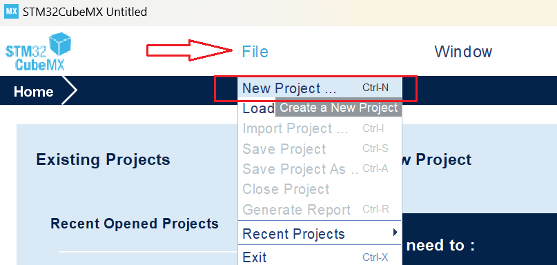
Launch STM32CubeMX: Open the STM32CubeMX application on your system.
Create a New Project: Open STM32CubeMX and navigate to File > New Project > Create New Project.
Select Your Board OR MCU: Go to the Board Selector tab and enter the name of your STM32 development board. For this tutorial, we are using the NUCLEO-H563ZI board.
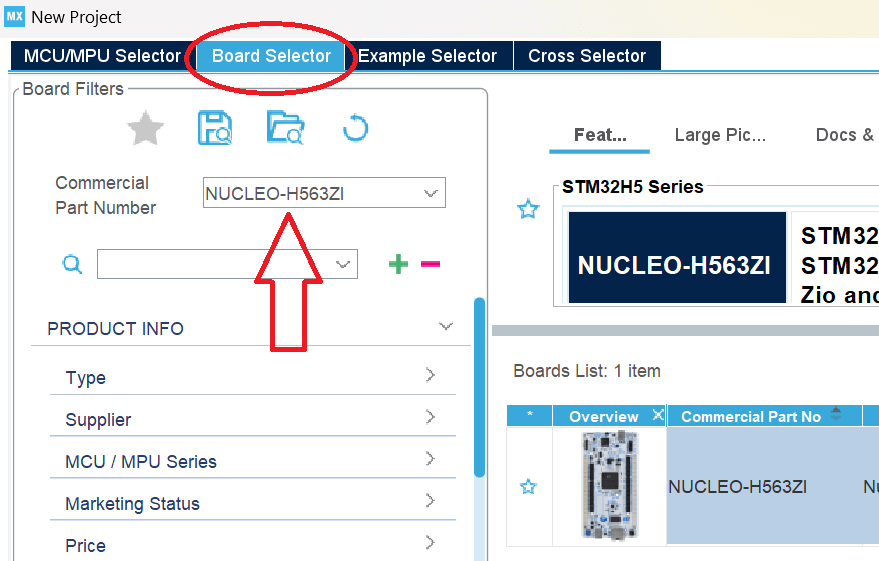
Click on Start Project and select without trustZone activated or with trustZone activated. I will select without trustZone activated here.

Step: -2 Pinout Configuration:
Navigate to the ‘Pinout & Configuration tab’ in STM32CubeMX. Identify the GPIO pin connected to the LED based on your board’s documentation. For instance, on the STM32H6ZI board, the user yellow LED (LD2) is connected to PF4 and user button PC13. In this example, we will configure PF4 as the LED pin and PC13 as Button pin.
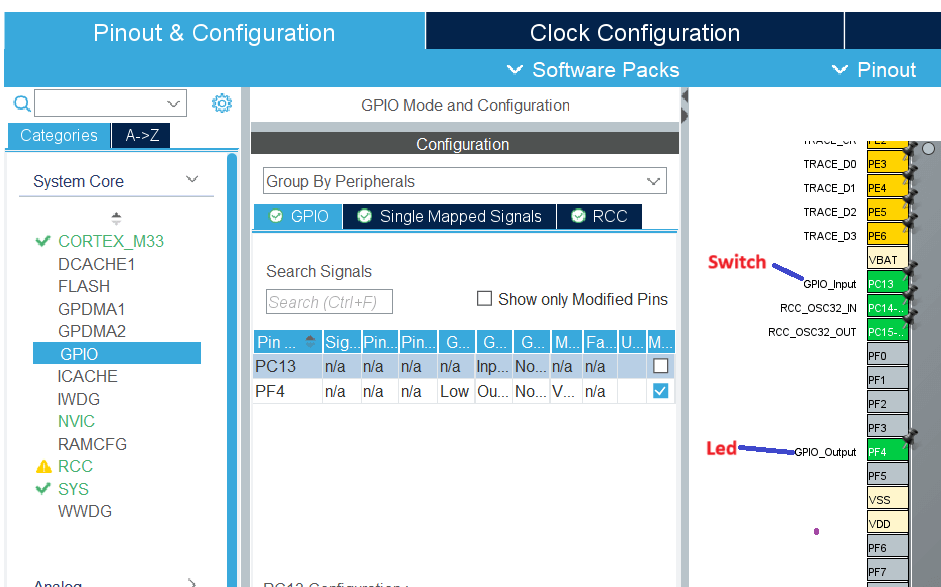
In the GPIO tab of STM32CubeMX, select PF4 to configure the LED and PC13 to configure the switch. Key settings include:
Setting for LED PF4:
- GPIO Output Level: Default is Low, change to High to turn on the LED.
- GPIO Mode: Set to Output Push-Pull, ideal for driving an LED.
- GPIO Pull-up/Pull-down: Default is None, adjust it no pull-up and no pull down.
- GPIO Maximum Output Speed: Default is Low for power saving; set it very high.
- User Label: Assign a custom label to identify and locate the pin easily.
Settings for Switch on PC13:
- GPIO Mode: Set to Input Mode, which is ideal for reading the state of a switch.
- GPIO Pull-up/Pull-down: By default, it is set to None. Here I adjust to this No Pull-up or No Pull-down. You can adjust this to depending on your circuit design.
- User Label: Assign a custom label to the pin to easily identify and locate it when using the Find menu.
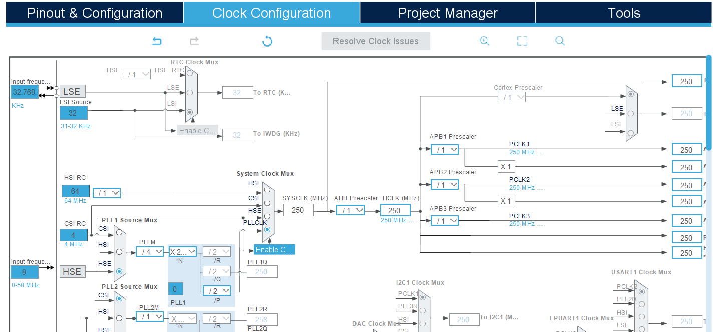
Step 3: Clock Configuration:
The Clock Configuration tab in STM32CubeMX offers a visual and interactive interface for setting up the clock system of your STM32 microcontroller. It allows you to configure various clock sources and adjust the frequencies for the core, peripherals, and buses.
Key Features:
- Clock Source Selection: Choose from internal oscillators (HSI, LSI) or external oscillators (HSE, LSE), or use a PLL (Phase-Locked Loop) for higher system frequencies.
- PLL Configuration: Fine-tune the PLL settings to achieve your desired system clock frequency.
- Bus Frequencies: Configure the AHB (HCLK) and APB (PCLK1/PCLK2) clock prescalers to optimize performance based on your application requirements.
- Real-Time Visualization: See immediate updates to the system clock frequencies as you make adjustments, allowing you to visualize the impact of your settings.
- Error Detection: STM32CubeMX automatically validates your clock settings to ensure they comply with the microcontroller’s clock limits, preventing potential configuration issues.
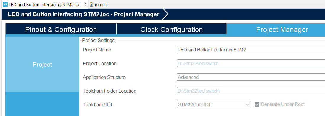
Step: -4 Configure the project and generate source code:
After setting up your clock configuration, proceed to the Project Manager tab to finalize your project settings and generate the source code. In the Project tab:
- Fill the Project Name and Project Location fields.
- Set Toolchain/IDE to STM32CubeIDE.
Before generating the source code, navigate to the Code Generator tab and ensure the following options are enabled for a seamless development experience:
- STM32Cube Firmware Library Package:
- Select Copy all used libraries into the project folder to include all necessary libraries directly in your project, ensuring portability and ease of use.
- Generated Files:
- Enable Keep user code when regenerating to preserve any custom code written in user-defined sections within the STM32CubeMX-generated files during subsequent code generation.
Step: -5 Edit the generated source code:
Now you need to customize the generated source code as per your requirements. For this example, we will create a simple program to control LED using a button. So, let’s modify the code to achieve this.
The following code has been modified to blink the LED connected to PF4 on my board by pressing a button that connected to PC13.
#ifdef __cplusplus
extern "C"
{
#endif
#include "stm32h5xx_hal.h"
#ifdef __cplusplus
}
#endif

/**
 * @brief Debounce delay in milliseconds.
 *
 * Defines the debounce delay time to filter out spurious button presses caused by bouncing.
 */
#define DEBOUNCE_DELAY 200

/**
 * @brief Define the button pin (PC13) and LED pin (PF4).
 */
#define BUTTON_PIN GPIO_PIN_13
#define LED_PIN GPIO_PIN_4

/**
 * @file main.c
 * @brief This code is modified by AticleWorld for demonstration purposes.
 *
 * @details The provided code is shared "as-is" without any warranties or guarantees
 * of performance, suitability, or correctness. Use it at your own discretion and risk.
 */
/**
 * @brief Enumeration to indicate status.
 */
typedef enum
{
  eSuccess = 0, /**< Indicates successful operation */
  eError = 1 /**< Indicates error in operation */
} eStatus;


/**
 * @brief Enumeration to indicate status.
 */
typedef enum
{
  eLedOff = 0, /**< Indicates led off */
  eLedOn = 1 /**< Indicates led on */
} eLedOnOffStatus;

/**
 * @brief Flag to track LED state.
 *
 * This flag is used to keep track of the current state of the LED.
 * The LED is toggled when the button is pressed.
 */
static eLedOnOffStatus ledState = eLedOff; // Track LED state (0 = OFF, 1 = ON)
static uint8_t buttonWasPressed = 0; // Flag to prevent multiple toggles without release

/**
 * @brief Function to check if the button is pressed with debounce.
 *
 * This function checks if the button has been pressed and applies debounce logic
 * to avoid false readings caused by the mechanical bouncing of the switch.
 *
 * @retval 1 Button is pressed (active low).
 * @retval 0 Button is not pressed.
 */

int isButtonPressed(void)
{
  static uint32_t last_time = 0;  // Time of last state change
  static uint8_t last_state = GPIO_PIN_SET; // Last button state (not pressed)
  int hasButtonPressed = 0;

  uint8_t current_state = HAL_GPIO_ReadPin(GPIOC, BUTTON_PIN); // Read current button state

  // If the state has changed (button press or release)
  if (current_state != last_state)
  {
    last_time = HAL_GetTick();  // Reset the debounce timer
  }

  // If the state has been stable for more than 50ms (debounce period)
  if ((HAL_GetTick() - last_time) > DEBOUNCE_DELAY) // 50ms debounce time
  {
    if (current_state == GPIO_PIN_RESET && !buttonWasPressed) // Button pressed (active low)
    {
      buttonWasPressed = 1;  // Mark the button as pressed
      last_state = current_state;  // Update the state
      hasButtonPressed = 1;  // Button press detected
    }
    else if (current_state == GPIO_PIN_SET)
    {
      buttonWasPressed = 0;  // Reset the flag when button is released
    }
  }

  last_state = current_state;  // Update the last state for the next iteration
  return hasButtonPressed;  // No button press detected
}

/**
 * @brief Configures the system clock.
 *
 * This function initializes the RCC (Reset and Clock Control) to configure
 * the system clock using the HSE (High-Speed External) oscillator with the PLL.
 *
 * @retval eSuccess if the configuration is successful.
 * @retval eError if an error occurs during configuration.
 */
eStatus SystemClock_Config(void)
{
  eStatus ret = eSuccess; // Default status
  RCC_OscInitTypeDef RCC_OscInitStruct =
  { 0 };
  RCC_ClkInitTypeDef RCC_ClkInitStruct =
  { 0 };
  /** Configure the main internal regulator output voltage */
  __HAL_PWR_VOLTAGESCALING_CONFIG(PWR_REGULATOR_VOLTAGE_SCALE0);
  while (!__HAL_PWR_GET_FLAG(PWR_FLAG_VOSRDY))
  {
  }
  /** Initialize the RCC Oscillators */
  RCC_OscInitStruct.OscillatorType = RCC_OSCILLATORTYPE_HSE;
  RCC_OscInitStruct.HSEState = RCC_HSE_BYPASS;
  RCC_OscInitStruct.PLL.PLLState = RCC_PLL_ON;
  RCC_OscInitStruct.PLL.PLLSource = RCC_PLL1_SOURCE_HSE;
  RCC_OscInitStruct.PLL.PLLM = 4;
  RCC_OscInitStruct.PLL.PLLN = 250;
  RCC_OscInitStruct.PLL.PLLP = 2;
  RCC_OscInitStruct.PLL.PLLQ = 2;
  RCC_OscInitStruct.PLL.PLLR = 2;
  RCC_OscInitStruct.PLL.PLLRGE = RCC_PLL1_VCIRANGE_1;
  RCC_OscInitStruct.PLL.PLLVCOSEL = RCC_PLL1_VCORANGE_WIDE;
  RCC_OscInitStruct.PLL.PLLFRACN = 0;
  if (HAL_RCC_OscConfig(&RCC_OscInitStruct) != HAL_OK)
  {
    ret = eError;
  }
  if (ret != eError)
  {
    /** Initialize the CPU, AHB, and APB buses clocks */
    RCC_ClkInitStruct.ClockType =
    RCC_CLOCKTYPE_HCLK | RCC_CLOCKTYPE_SYSCLK |
    RCC_CLOCKTYPE_PCLK1 | RCC_CLOCKTYPE_PCLK2 | RCC_CLOCKTYPE_PCLK3;
    RCC_ClkInitStruct.SYSCLKSource = RCC_SYSCLKSOURCE_PLLCLK;
    RCC_ClkInitStruct.AHBCLKDivider = RCC_SYSCLK_DIV1;
    RCC_ClkInitStruct.APB1CLKDivider = RCC_HCLK_DIV1;
    RCC_ClkInitStruct.APB2CLKDivider = RCC_HCLK_DIV1;
    RCC_ClkInitStruct.APB3CLKDivider = RCC_HCLK_DIV1;
    if (HAL_RCC_ClockConfig(&RCC_ClkInitStruct, FLASH_LATENCY_5) != HAL_OK)
    {
      ret = eError;
    }
    if (ret != eError)
    {
      /** Configure the programming delay */
      __HAL_FLASH_SET_PROGRAM_DELAY(FLASH_PROGRAMMING_DELAY_2);
    }
  }
  return ret;
}
/**
 * @brief Initializes the GPIO pins.
 *
 * This function configures GPIOF pin 4 as a push-pull output
 * for controlling an LED.
 *
 * @retval None
 */
static void MX_GPIO_Init(void)
{
  GPIO_InitTypeDef GPIO_InitStruct =
  { 0 };
  /* Enable the GPIOF clock */
  __HAL_RCC_GPIOF_CLK_ENABLE();
  __HAL_RCC_GPIOC_CLK_ENABLE();
  /* Configure GPIO pin output level */
  HAL_GPIO_WritePin(GPIOF, GPIO_PIN_4, GPIO_PIN_RESET);
  /* Configure GPIO pin PF4 */
  GPIO_InitStruct.Pin = GPIO_PIN_4;
  GPIO_InitStruct.Mode = GPIO_MODE_OUTPUT_PP;
  GPIO_InitStruct.Pull = GPIO_NOPULL;
  GPIO_InitStruct.Speed = GPIO_SPEED_FREQ_VERY_HIGH;
  HAL_GPIO_Init(GPIOF, &GPIO_InitStruct);

  /* Configure GPIO pin PC13 */
  GPIO_InitStruct.Pin = GPIO_PIN_13;
  GPIO_InitStruct.Mode = GPIO_MODE_INPUT;
  GPIO_InitStruct.Pull = GPIO_NOPULL;
  GPIO_InitStruct.Speed = GPIO_SPEED_FREQ_VERY_HIGH;
  HAL_GPIO_Init(GPIOC, &GPIO_InitStruct);
}
/**
 * @brief Main function.
 *
 * The entry point of the program initializes the HAL library, configures the
 * system clock, initializes GPIO, and enters an infinite loop.
 *
 * @retval int This function does not return.
 */
int main(void)
{
  eStatus ret = eSuccess;
  /* Initialize the HAL Library */
  HAL_StatusTypeDef ok = HAL_Init();
  if (ok == HAL_OK)
  {
    /* Configure the system clock */
    ret = SystemClock_Config();
    if (ret != eError)
    {
      /* Initialize all configured peripherals */
      MX_GPIO_Init();

      while (1)
      {
        // Check if the button is pressed with debouncing
        if (isButtonPressed())
        {
          // Toggle the LED state
          if (ledState == eLedOff)
          {
            HAL_GPIO_WritePin(GPIOF, LED_PIN, GPIO_PIN_SET); // Turn ON LED
            ledState = eLedOn;
          }
          else
          {
            HAL_GPIO_WritePin(GPIOF, LED_PIN, GPIO_PIN_RESET); // Turn OFF LED
            ledState = eLedOff;
          }
        }
      }
    }
  }
  else
  {
    ret = eError;
  }
  return (ret == eSuccess);
}
How code works:
- In the above code, when the button is pressed, isButtonPressed() function detects the press after the debounce period (100ms). After detecting the valid button press LED state accordingly.
- After the button is released, the system will reset the flag (buttonWasPressed = 0) to detect the next press.
- This prevents the LED from toggling multiple times during a single button press.
STM32 GPIO C++ Source Code to Control LED Using a Button Input:
#include "stdio.h"

extern "C"
{
#include "stm32h5xx_hal.h"
}

// Debounce delay in milliseconds
constexpr uint32_t DEBOUNCE_DELAY = 100;

// Enum for LED states
enum class LedState
{
   Off,
   On
};

// Enum for Status
enum class Status
{
   Success,
   Error
};

// Abstract class for GPIO handling
class IGpio
{
public:
   virtual void WritePin(uint16_t pin, GPIO_PinState state) = 0;
   virtual GPIO_PinState ReadPin(uint16_t pin) = 0;
   virtual ~IGpio() = default;
};

// Concrete GPIO class
class HalGpio : public IGpio
{
public:
   void WritePin(uint16_t pin, GPIO_PinState state) override
   {
      HAL_GPIO_WritePin(GPIOF, pin, state);
   }
   GPIO_PinState ReadPin(uint16_t pin) override
   {
      return HAL_GPIO_ReadPin(GPIOC, pin);
   }
};

// Button class with debounce logic
class Button
{
public:
   Button(IGpio& gpio, uint16_t pin)
         : m_rGpio(gpio), m_pin(pin), m_lastState(GPIO_PIN_SET), m_lastDebounceTime(0), m_pressed(false)
   {
   }

   bool isButtonPressed()
   {
      bool hasButtonPressed = false;
      GPIO_PinState currentState = m_rGpio.ReadPin(m_pin);
      uint32_t currentTime = HAL_GetTick();

      if (currentState != m_lastState)
      {
         m_lastDebounceTime = currentTime; // Reset debounce timer
      }

      if ((currentTime - m_lastDebounceTime) > DEBOUNCE_DELAY)
      {
         if (currentState == GPIO_PIN_RESET && !m_pressed)
         {
            m_pressed = true; // Button pressed
            hasButtonPressed = true;
            m_lastState = currentState;
         }
         else if (currentState == GPIO_PIN_SET)
         {
            m_pressed = false; // Button released
         }
      }

      m_lastState = currentState;
      return hasButtonPressed;
   }

private:
   IGpio& m_rGpio;
   uint16_t m_pin;
   GPIO_PinState m_lastState;
   uint32_t m_lastDebounceTime;
   bool m_pressed;
};

// LED controller class
class LedController
{
public:
   LedController(IGpio& gpio, uint16_t pin) : m_rGpio(gpio), m_pin(pin), m_state(LedState::Off) {}

   void Toggle()
   {
      if (m_state == LedState::Off)
      {
         m_rGpio.WritePin(m_pin, GPIO_PIN_SET);
         m_state = LedState::On;
      }
      else
      {
         m_rGpio.WritePin(m_pin, GPIO_PIN_RESET);
         m_state = LedState::Off;
      }
   }

private:
   IGpio& m_rGpio;
   uint16_t m_pin;
   LedState m_state;
};

// System clock configuration
Status ConfigureSystemClock()
{
   RCC_OscInitTypeDef RCC_OscInitStruct = {};
   RCC_ClkInitTypeDef RCC_ClkInitStruct = {};

   __HAL_PWR_VOLTAGESCALING_CONFIG(PWR_REGULATOR_VOLTAGE_SCALE0);
   while (!__HAL_PWR_GET_FLAG(PWR_FLAG_VOSRDY))
   {
   }

   RCC_OscInitStruct.OscillatorType = RCC_OSCILLATORTYPE_HSE;
   RCC_OscInitStruct.HSEState = RCC_HSE_BYPASS;
   RCC_OscInitStruct.PLL.PLLState = RCC_PLL_ON;
   RCC_OscInitStruct.PLL.PLLSource = RCC_PLL1_SOURCE_HSE;
   RCC_OscInitStruct.PLL.PLLM = 4;
   RCC_OscInitStruct.PLL.PLLN = 250;
   RCC_OscInitStruct.PLL.PLLP = 2;
   RCC_OscInitStruct.PLL.PLLQ = 2;
   RCC_OscInitStruct.PLL.PLLR = 2;
   RCC_OscInitStruct.PLL.PLLRGE = RCC_PLL1_VCIRANGE_1;
   RCC_OscInitStruct.PLL.PLLVCOSEL = RCC_PLL1_VCORANGE_WIDE;
   RCC_OscInitStruct.PLL.PLLFRACN = 0;

   if (HAL_RCC_OscConfig(&RCC_OscInitStruct) != HAL_OK)
   {
      return Status::Error;
   }

   RCC_ClkInitStruct.ClockType =
         RCC_CLOCKTYPE_HCLK | RCC_CLOCKTYPE_SYSCLK | RCC_CLOCKTYPE_PCLK1 | RCC_CLOCKTYPE_PCLK2
| RCC_CLOCKTYPE_PCLK3;
   RCC_ClkInitStruct.SYSCLKSource = RCC_SYSCLKSOURCE_PLLCLK;
   RCC_ClkInitStruct.AHBCLKDivider = RCC_SYSCLK_DIV1;
   RCC_ClkInitStruct.APB1CLKDivider = RCC_HCLK_DIV1;
   RCC_ClkInitStruct.APB2CLKDivider = RCC_HCLK_DIV1;
   RCC_ClkInitStruct.APB3CLKDivider = RCC_HCLK_DIV1;

   if (HAL_RCC_ClockConfig(&RCC_ClkInitStruct, FLASH_LATENCY_5) != HAL_OK)
   {
      return Status::Error;
   }

   __HAL_FLASH_SET_PROGRAM_DELAY(FLASH_PROGRAMMING_DELAY_2);
   return Status::Success;
}

// GPIO initialization
void initGpio()
{
   GPIO_InitTypeDef GPIO_InitStruct = {};
   __HAL_RCC_GPIOF_CLK_ENABLE();
   __HAL_RCC_GPIOC_CLK_ENABLE();

   // Configure GPIOF pin 4
   HAL_GPIO_WritePin(GPIOF, GPIO_PIN_4, GPIO_PIN_RESET);
   GPIO_InitStruct.Pin = GPIO_PIN_4;
   GPIO_InitStruct.Mode = GPIO_MODE_OUTPUT_PP;
   GPIO_InitStruct.Pull = GPIO_NOPULL;
   GPIO_InitStruct.Speed = GPIO_SPEED_FREQ_VERY_HIGH;
   HAL_GPIO_Init(GPIOF, &GPIO_InitStruct);

   // Configure GPIOC pin 13
   GPIO_InitStruct.Pin = GPIO_PIN_13;
   GPIO_InitStruct.Mode = GPIO_MODE_INPUT;
   GPIO_InitStruct.Pull = GPIO_NOPULL;
   GPIO_InitStruct.Speed = GPIO_SPEED_FREQ_VERY_HIGH;
   HAL_GPIO_Init(GPIOC, &GPIO_InitStruct);
}

// Main application
class LedControlApplication
{
public:
   LedControlApplication(IGpio& gpio) : m_rGpio(gpio), m_button(gpio, GPIO_PIN_13), m_led(gpio, GPIO_PIN_4) {}

   void Run()
   {
      while (true)
      {
         if (m_button.isButtonPressed())
         {
            m_led.Toggle();
         }
         // Add delay to prevent 100% CPU usage
         HAL_Delay(10);
      }
   }

private:
   IGpio& m_rGpio;
   Button m_button;
   LedController m_led;
};

int main()
{
   HAL_Init();

   if (ConfigureSystemClock() == Status::Error)
   {
      return static_cast<int>(Status::Error);
   }

   initGpio();
   HalGpio gpio;
   LedControlApplication app(gpio);
   app.Run();

   return static_cast<int>(Status::Success);
}
I hope this piece of code helps you in your STM32 projects! If you have any questions or need further clarification, feel free to leave a comment below I would be happy to assist you. Don’t hesitate to share any challenges you’ve faced or insights you’ve gained while working with GPIO pins.
If you found this guide useful, please consider sharing it with your friends and colleagues on your social media platforms. Your support helps others discover this resource and strengthens the STM32 community. Thanks for sharing!
Happy Coding. 🤩
Exercises for you:
- Build a counter that increments on each button press and shows the value on LEDs or an LCD.
- Create a simple password system using a sequence of button presses.
- Make a stopwatch with Start/Stop and Reset buttons.
- Use a long press to switch the device into low-power mode.
- Add button-based control to enhance any existing project.
Related posts:
- Map-Based Method for GPIO Alternate Function Configuration.
- Embedded C interview questions and answers.
- Interview questions on C/C++ pointers.
- How do I read an STM32 button input?
- Is interrupt mode better for STM32 button input?