In this post, you will learn STM32 button LED bare metal programming by controlling an LED with a push button on an STM32 microcontroller. We do this without using HAL, LL, or other libraries.
By working directly with hardware registers and adding software debouncing, this example shows how to manage CPU execution, system clock setup, and low-level GPIO control. You’ll also see how software debouncing fixes the common problem of mechanical button bounce.
Unlike simple LED blinking tutorials, this example tackles a real hardware issue that often causes bugs in embedded systems.
The LED and button are just tools. The real objective is to understand:
- How GPIO input works internally
- How the CPU reads pin states from hardware registers
- Why raw input signals are unreliable
- How software debouncing fixes false triggers
If you understand this article, you will understand one of the most common causes of bugs in embedded products.
Hardware Setup:
Before writing a single line of code, verify the physical wiring. Bare-metal programming leaves zero room for assumptions, one small mistake can cost you hours of debugging.
Below is the list of components and tools used in this blog post.
| Component Name | Quantity | Purchase Link |
|---|---|---|
| STM32 NUCLEO Development Board | 1 | Amazon |
| LED | 1 | Amazon |
| Resistor 220 ohm | 1 | Amazon |
| Breadboard | 1 | Amazon |
| Jumper wire pack | 1 | Amazon |
| USB Mini-B cable | 1 | Amazon |
For troubleshooting, some extremely useful test equipment
| Equipment Name | Purchase Link |
|---|---|
| Best Oscilloscope for Professionals | Amazon |
| Best Oscilloscope for Beginners and Students | Amazon |
| Logic Analyzer | Amazon |
| Best Budget Multimeter | Amazon |
| Adjustable Bench Power Supply | Amazon |
Why Control an LED Using a Button (Bare Metal)?
Blinking an LED confirms that the CPU is running.
But controlling an LED using a push button proves something more important: the microcontroller can sense the outside world and react to real hardware events.
In real embedded systems, the MCU constantly reads external inputs such as:
- Push buttons.
- Sensors.
- Interrupt signals.
- Communication lines
To a beginner, a button may appear simple, but at the hardware level, it involves GPIO input buffers, pull-up/pull-down resistors, and signal stability. If any of these are misunderstood or misconfigured, things stop working.
A Real GPIO Debugging Story:
Before diving deep into this article, it’s important to understand why learning bare-metal programming matters and how it helps you become a better embedded engineer.
While writing a proof-of-concept (PoC), I once spent several hours debugging a push button that simply refused to work on an STM32 board.
The code looked correct. To rule out a software issue, I even forced the LED-blinking logic to execute unconditionally, and the LED blinked perfectly. There were no compiler warnings and no runtime errors.
So, what was wrong?
Every time I pressed the user button, the LED-blinking code did not execute. I double-checked the GPIO configuration multiple times, and everything looked correct at first glance.
Later, I realized that the Nucleo board already provides an external pull-down resistor on the user button pin. By enabling the internal pull-up, the button logic behaved incorrectly.
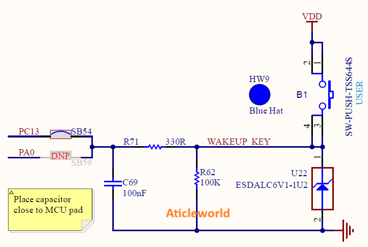
Look at the circuit below. It uses a resistor called R62 (100kΩ) to keep the input pin connected to ground (0V), so the pin normally reads a low signal (Logic 0). This resistor is called a pull-down resistor, and it stops the pin from “floating” and giving random values.
When you press the button, it connects the pin directly to the power supply (3.3V), which is a high signal (Logic 1). Because this path has much less resistance than R62, the pin quickly changes to high.
There are also a small capacitor (C69) and another resistor (R71) that work together as a simple filter. This filter smooths out the tiny quick changes caused by the button’s mechanical bouncing, so the MCU sees a clean, stable signal.
Finally, a component called U22 protects the microcontroller by safely redirecting any sudden high-voltage spikes caused by static electricity (ESD).
Now you might be wondering why the circuit doesn’t work properly when the internal pull-up resistor is enabled. Let me explain why that happens.
What Happens When You Enable the Internal Pull-Up Resistor?
When the internal pull-up resistor (typically around 30–50 kΩ) is enabled while an external pull-down resistor (for example, 100 kΩ) is already present, the two resistors work against each other. Together, they form a voltage divider between VCC and GND.
As a result:
- The GPIO pin no longer sees a clean logic LOW when the button is released
- The pin voltage can sit at an intermediate level (around 2–2.5 V, depending on VDD and resistor values)
- This level may be interpreted as logic HIGH or may fluctuate, leading to unstable or undefined behavior
From the MCU’s perspective, the button may appear to be permanently pressed or may behave unpredictably. Once the internal pull-up resistor was explicitly disabled at the register level, the voltage divider was eliminated, and the issue was resolved immediately.

Bare-Metal Reality: GPIO Inputs Do Nothing by Default:
After a reset, an STM32 microcontroller powers up in a neutral and power-safe state. The hardware does not assume how you want to use any GPIO pin:
- Peripheral clocks are disabled to reduce power consumption
- GPIO pins are set to analog or floating input mode
- Internal pull-up and pull-down resistors are turned off
- Reading an unconfigured input pin can give unpredictable results
This behavior is intentional. It prevents accidental current flow, signal contention, and unnecessary power usage.
Bare-metal programming teaches you to take full control of the hardware by requiring you to:
- Manually enable the peripheral clock.
- Explicitly configure the GPIO mode.
- Clearly define the pin’s electrical characteristics (pull-ups, speed, output type)
Once you understand this process, GPIO behavior stops feeling “mysterious” and becomes completely predictable.
Button Logic: Active High vs Active Low:
Push buttons are typically wired in one of two ways:
| Configuration | Wiring | Pressed State | Released State |
|---|---|---|---|
| Active High | Pin → Button → VCC | Logic 1 | Logic 0 (Pull-down) |
| Active Low | Pin → Button → GND | Logic 0 | Logic 1 (Pull-up) |
The 3-Step Hardware Handshake (Button & LED)
When working with a push button and an LED in STM32 bare-metal programming, the hardware always follows the same 3-step rule:
In STM32 bare-metal programming, this rule applies to every peripheral: hardware does exactly what you configure, no more, no less. Missing even a single step can result in incorrect button readings or unpredictable LED behavior.
So, the simple idea here:
- Clock — Wake up the GPIO peripheral.
- Configuration — Tell the pins how to behave.
- Action — Read the button and control the LED.
Step 1: Enable the GPIO Clock (Wake Up the Hardware)
After a reset, almost all STM32 peripherals are clock-gated to save power. A peripheral without a clock is effectively inactive.
If the GPIO clock is not enabled:
- Button reads may always return 0
- LED writes may be ignored
- The CPU may even crash in some cases
Step 2: Configure Button and LED Pins:
Once the clock is enabled, the GPIO pins must be explicitly configured.
Button Pin (Input)
For a push button:
- Set the pin to Input mode
- Enable pull-up or pull-down based on how the button is wired (See schematics)
Example:
- Active LOW button → Enable pull-up
- Active HIGH button → Enable pull-down
Without this, the input may float and trigger randomly.
LED Pin (Output)
At reset, GPIO pins default to Analog mode. This means:
- The LED pin cannot drive any output signal
- Writing to output registers (ODR/BSRR) has no visible effect on the pin state
To properly control an LED, you need to:
- Configure the LED pin in Output mode
- Use Push-Pull output type in most cases (for direct drive)
- Select a low or medium speed setting, which is sufficient for LED toggling and reduces EMI
Step 3: Read the Button and Control the LED
Once both pins are configured:
- Read the button state from the IDR register
- Decide what to do
- Set or reset the LED pin using the BSRR register
Typical Logic
- Button pressed → LED ON
- Button released → LED OFF
Whether a HIGH or LOW turns the LED ON depends on how it is wired.
| Button Type | Button Pressed (IDR) | LED Action |
|---|---|---|
| Active LOW | 0 | Turn LED ON |
| Active HIGH | 1 | Turn LED ON |
Now it is time to write the code.
The following example demonstrates one of the most fundamental hardware sanity checks on an STM32H5 device: reading a push button input and controlling an LED using direct register access. No HAL. No LL. No high-level abstractions, just the CPU, the registers, and the silicon.
#include "stm32h563xx.h"

/* ----------------------------------------------------
 * LD1: PB0
 * B1 : PC13 (Active LOW, Tamper-capable pin)
 * ---------------------------------------------------- */

#define LED_PIN_POS (0U)
#define LED_PIN (1U << LED_PIN_POS)

#define BTN_PIN_POS (13U)
#define BTN_PIN (1U << BTN_PIN_POS)

#define LED_ON() (GPIOB->BSRR = LED_PIN)
#define LED_OFF() (GPIOB->BSRR = (LED_PIN << 16U))

static void delay(volatile uint32_t count)
{
  while (count--)
  {
    __NOP();
  }
}

int main(void)
{
  uint8_t last_button_state = 1U; // Released (Active LOW)

  /* ----------------------------------------------------
   * 1. Enable GPIO clocks
   * ---------------------------------------------------- */
  RCC->AHB2ENR |= RCC_AHB2ENR_GPIOBEN | RCC_AHB2ENR_GPIOCEN;
  (void) RCC->AHB2ENR; // Ensure clock is stable

  /* ----------------------------------------------------
   * 2. Configure LED (PB0) as output
   * ---------------------------------------------------- */
  GPIOB->MODER &= ~(3U << (LED_PIN_POS * 2U));
  GPIOB->MODER |= (1U << (LED_PIN_POS * 2U)); // Output mode

  GPIOB->OTYPER &= ~LED_PIN;                     // Push-pull
  GPIOB->OSPEEDR &= ~(3U << (LED_PIN_POS * 2U)); // Low speed
  GPIOB->PUPDR &= ~(3U << (LED_PIN_POS * 2U));   // No pull

  LED_OFF();

  /* ----------------------------------------------------
   * 3. Configure Button (PC13)
   * ---------------------------------------------------- */
  GPIOC->MODER &= ~(3U << (BTN_PIN_POS * 2U)); // Input mode
  GPIOC->PUPDR &= ~(3U << (BTN_PIN_POS * 2U)); // No pull
  GPIOC->OSPEEDR &= ~(3U << (BTN_PIN_POS * 2U)); // LOW speed (important for PC13)

  /* ----------------------------------------------------
   * 4. Main loop with software debounce
   * ---------------------------------------------------- */
  while (1)
  {
    uint8_t raw_state = (GPIOC->IDR & BTN_PIN) ? 1U : 0U;

    if (raw_state != last_button_state)
    {
      delay(30000); // Slightly longer debounce for PC13

      raw_state = (GPIOC->IDR & BTN_PIN) ? 1U : 0U;

      if (raw_state != last_button_state)
      {
        last_button_state = raw_state;

        if (raw_state == 1U)
        {
          LED_ON(); // Button pressed
        }
        else
        {
          LED_OFF(); // Button released
        }
      }
    }
  }
}
Code Walkthrough: Button-Controlled LED with Software Debounce:
The above C program reads the onboard user button (PC13) and controls the onboard LED (PB0) on the STM32H563 Nucleo board using direct register access. Also, a simple software debounce mechanism is implemented to ensure reliable button detection.
Let’s now walk through the code step by step and understand how it works.
1. Device Header:
#include "stm32h563xx.h"
This header file provides:
- Base addresses of peripherals
- Register structures (RCC, GPIO, etc.)
- Bit definitions and masks specific to STM32H563.
Without this file, the compiler has no knowledge of the STM32H563 register map or peripheral layout.
2. LED and Button Bit Definitions:
#define LED_PIN_POS (0U)
#define LED_PIN     (1U << LED_PIN_POS)

#define BTN_PIN_POS (13U)
#define BTN_PIN     (1U << BTN_PIN_POS)
These macros define:
- PB0 as the LED pin
- PC13 as the button pin
- Using bit masks instead of raw numbers to improves readability.
3. Atomic GPIO Control Using BSRR
#define LED_ON()  (GPIOB->BSRR = LED_PIN)

#define LED_OFF() (GPIOB->BSRR = (LED_PIN << 16U))
Here, the BSRR (Bit Set/Reset Register) is used to control the LED.
- Bits 0–15 → Set output HIGH
- Bits 16–31 → Reset output LOW
Why BSRR?
- Atomic operation (single bus write)
- No read-modify-write hazards
- Safe even in interrupt-driven systems.
4. Simple Blocking Delay:
static void delay(volatile uint32_t count)
A simple blocking delay implemented using __NOP(). This delay is not cycle-accurate or time-precise, but it is sufficient to demonstrate that the CPU is running and executing instructions.
5. Button State Tracking Variable:
uint8_t last_button_state = 1U; // Released (Active LOW)
The user button on PC13 is Active LOW:
- 0 → Button pressed
- 1 → Button released
This variable stores the previous stable state of the button, allowing the code to detect state changes instead of reacting to noise.
6. Enable GPIO Clock:
RCC->AHB2ENR |= RCC_AHB2ENR_GPIOBEN;

(void)RCC->AHB2ENR;
Enabling a clock is not instantaneous. It takes a few CPU cycles for the clock signal to propagate through the silicon and reach the peripheral. If you enable the clock and immediately access the GPIO registers in the very next instruction, the write may fail because the peripheral is not ready yet.
To avoid this, we perform a dummy read:
(void)RCC->AHB2ENR;
This forces the CPU to complete the bus transaction, ensuring the peripheral clock is active before we continue.
7. Configure PB0 as LED Output:
GPIOB->MODER &= ~(3U << (LED_PIN_POS * 2U));
GPIOB->MODER |= (1U << (LED_PIN_POS * 2U)); // Output mode

GPIOB->OTYPER &= ~LED_PIN;                     // Push-pull
GPIOB->OSPEEDR &= ~(3U << (LED_PIN_POS * 2U)); // Low speed
GPIOB->PUPDR &= ~(3U << (LED_PIN_POS * 2U)); // No pull
PB0 is configured as a general-purpose output to drive the LED. The GPIO mode is set to Output, allowing the pin to actively control the LED state. The output type is push-pull, which can drive both HIGH and LOW without needing an external pull-up resistor—ideal for LEDs.
The output speed is kept low, since LEDs do not require fast edges. This reduces EMI and power consumption. No internal pull-up or pull-down is enabled because the pin is used as an output. Finally, the LED is explicitly turned OFF during initialization to ensure a known, safe hardware state before the main loop starts.
8. Configure Button Input (PC13):
GPIOC->MODER &= ~(3U << (BTN_PIN_POS * 2U)); // Input mode
GPIOC->PUPDR &= ~(3U << (BTN_PIN_POS * 2U)); // No pull
GPIOC->OSPEEDR &= ~(3U << (BTN_PIN_POS * 2U)); // Low speed
Important notes about PC13:
- It is a tamper-capable pin
- Internally weak compared to other GPIOs
- Sensitive to noise and fast edges
9. Main Loop with Software Debouncing
The program keeps checking the button pin continuously. It reacts only when the button state changes, so keeping the button pressed does not cause repeated actions.
A short delay is added to ignore the quick on-off noise that occurs when the button is pressed or released. After this delay, the button is checked again to confirm the change is real.
Result:
- Button pressed → LED turns ON
- Button released → LED turns OFF
This simple method makes button reading stable and reliable without extra hardware.
FAQ: STM32 Button & LED Bare-Metal Programming:
Q1: Why does my button read wrong values?
Mechanical switches “bounce” (vibrate) when pressed, creating noisy signals. You need debouncing (either using S/W or H/W) to filter this noise and pull resistors to prevent floating inputs.
Q2: What is software debouncing?
It is a code technique that waits a few milliseconds for the signal to stabilize before registering a press, filtering out false triggers without requiring extra hardware.
Q3: How do I choose pull-up vs. pull-down?
If the button connects to GND, use a pull-up resistor. If it connects to VCC, use a pull-down resistor. Never mix internal and external resistors on the same pin.
Q4: Why is my PC13 button acting weird?
On many STM32 boards (like Nucleo), PC13 has an external pull-down resistor. Enabling the internal pull-up creates a conflict. Disable the internal pull-up for this pin.
Q5: Is hardware debouncing enough?
Hardware debouncing with RC circuits works well, but software debouncing is preferred in industry because it saves components and board space.
Q6: Why use Direct Register Access over HAL?
Direct register access offers lower latency, reduced code size, and full control over the hardware. HAL adds overhead and hides many details.
Q7: What is a “floating input”?
A floating input is a pin not connected to VCC or GND, which can pick up electrical noise like an antenna. Always fix this by configuring appropriate pull resistors.
Q8: How do I ensure the GPIO clock is enabled?
Due to bus delays, the clock might not start instantly. Always perform a dummy read of the clock enable register immediately after writing to it to ensure stability.
Q9: Why does my LED not turn on even though the code looks correct?
Verify that the GPIO pin is configured as output with the correct mode, speed, and output type (push-pull/open-drain). Also, confirm the GPIO clock is enabled and the LED wiring and polarity (active-high/low) are correct.
Q10: Why does reading GPIO input sometimes show stale or incorrect values?
Reading GPIO registers immediately after configuration or clock enable can cause unreliable results. Ensure clocks are stable and add small delays if necessary.
Q11: Can enabling internal pull-up or pull-down resistors increase power consumption?
Yes, internal pull resistors can cause small static currents, especially if the pin is externally driven. This can impact battery-powered or low-power designs.
Related posts:
- STM32 Bare-Metal LED Blink Guide: Blink an LED Without HAL.
- Blinking an LED on STM32: Step-by-Step Guide.
- STM32 GPIO Button and LED Control – Understanding STM32 Button Input.
- STM32 GPIO tutorial: Modes, Functions, and Configuration
- Map-Based Method for GPIO Alternate Function Configuration.