In electronics, whether you are designing a PCB, writing firmware for a microcontroller, or troubleshooting power issues, resistors are everywhere. Among them, pull-up resistors are one of the most common passive components. They may look simple, but they play a critical role in how signals behave, how stable your circuit is, and even how safely your system operates.
This article explains what Pull-Up Resistors are, why we need them, and how both hardware and firmware engineers use them in, real-world applications.
What Is a Pull-Up Resistor?
A pull-up resistor is one of the simplest and most common components you will see in digital electronics. You will find it on microcontrollers, sensors, and Arduino boards, …etc.

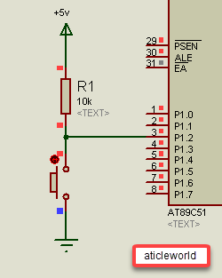
A pull-up resistor is simply a resistor connected from an input pin up to VDD, which is the positive power supply of the circuit. It ensures that an input pin stays at a stable and defined HIGH level (VDD) when a button or switch is not pressed. Without a pull-up resistor, the input pin becomes “floating,” meaning its voltage is undefined. In this state, leakage currents and electrical noise (EMI) can easily make the input fluctuate randomly between HIGH and LOW, causing unpredictable behavior.
Why Do We Need a Pull-Up Resistor?
In electronic circuits, many digital input pins cannot maintain a stable logic level on their own. If you leave the pin unconnected, the input will float — meaning it may randomly read HIGH or LOW depending on noise, humidity, nearby signals, or even your finger touching the wire. A pull-up resistor keeps the pin HIGH when nothing else is driving it.
Example: Button With Pull-Up
- When the button is not pressed, the resistor keeps the pin HIGH.
- When the button is pressed, the pin goes LOW.
Without the pull-up, the pin would float, and you’d get random HIGH/LOW readings.
Some Real-World Problems Caused by Missing Pull-Ups:
Let’s see some real-life examples where things went wrong just because a pull-up resistor wasn’t used, and how adding it fixed the issue right away.
1. Button Press Triggering Randomly (False Triggering)
Problem: A microcontroller-based system would detect a button press even when nobody touched it. Sometimes the device would reboot or enter a menu by itself.
Cause: The input pin connected to the button was floating. Small noise, static charge, or even a hand nearby caused the pin to jump between HIGH and LOW.
Fix: Adding a pull-up resistor kept the input stable at HIGH until the button was actually pressed, completely eliminating false triggers.
2. I²C Bus Not Working Reliably:
Problem: Sensors on the I²C bus would randomly stop responding. Data was corrupted, and sometimes the entire bus hung.
Cause: I²C lines (SDA and SCL) require pull-up resistors to define the HIGH state. Without them, both lines float and cannot return to a proper HIGH level after being pulled LOW.
Fix: Adding the recommended 4.7k–10k pull-up resistors restored clean logic levels and made communication fully reliable.
3. Unexpected Interrupts in Embedded Systems
Problem: An external interrupt pin kept firing even though no interrupt source was connected.
Cause: The interrupt line was left floating. Any small EMI spike triggered the interrupt logic.
Fix: A pull-up resistor ensured the pin stayed HIGH by default, preventing false interrupt signals.
4. Relay or MOSFET Turning ON Randomly
Problem: A relay or MOSFET connected to a GPIO input would turn ON randomly for a moment, causing motors or LEDs to activate unexpectedly.
Cause: The control input was floating during boot or idle.
Fix: A pull-up resistor locked the pin to a known HIGH state, preventing accidental switching.
5. Arduino / MCU Reading Sensor Values Incorrectly
Problem: An Arduino project showed random temperature spikes and incorrect digital readings from sensors.
Cause: The digital output pin from the sensor floated when the sensor was not actively driving the line.
Fix: A pull-up resistor ensured a stable HIGH state, removing all random fluctuations.
How To Choose a Pull-Up Resistor Value:
Before we learn how to choose the right pull-up resistor value, we must first understand what “strong pull-up” and “weak pull-up” mean, and how each one affects the circuit’s behavior.
Strong Pull-Ups and Weak Pull-Ups:
A pull-up resistor doesn’t just set the input HIGH, its value decides how strong or weak that pull-up is. A lower-value resistor (like 1 kΩ or 4.7 kΩ) creates a stronger pull-up, and a higher-value resistor (like 47 kΩ or 100 kΩ) creates a weaker pull-up.
Here is the simple reason:
- A smaller resistor lets more current flow from VDD (I = V/R).
- More current means the input pin charges its tiny internal capacitance much faster. It charges the total node capacitance (pin + trace + switch) much faster → shorter rise time (τ = Rₚᵤₗₗ × Cₜₒₜₐₗ)
- It also gives much better noise immunity: any noise current injected into the pin creates a voltage change of only ΔV = Iₙₒᵢₛₑ × Rₚᵤₗₗ. With a lower resistor, this voltage change becomes very small, so noise has a much harder time disturbing the input, the pull-up “holds” the line firmly at HIGH
- It also overcomes leakage, long wires, switch moisture, or ESD diode leakage more easily.
| Pull-up Value | Current When LOW | Signal Rise Speed | Noise Immunity | Typical Use Case |
|---|---|---|---|---|
| 1 kΩ | High (3.3 mA) | Very fast | Excellent | High-speed, noisy lines |
| 4.7 kΩ | Medium-high | Fast | Very good | Buttons, long wires |
2. Higher resistor value = weaker pull-up
Now that you understand how the pull-up resistor value affects the circuit, you can choose the right value by simply remembering these two rules:
Rule 1: The Pull-Up Value Cannot Be Too High: If the resistor value is too large, the input pin may not rise fast enough or high enough to reach a valid logic HIGH. This happens because leakage currents and internal input currents create a voltage drop across a very large resistor.
Example: 8051 running at 5V, the input pin needs at least around 2V to be detected as a logic HIGH. If your pull-up resistor value is too large, the input pin may not rise fast enough or high enough. Because of small leakage currents inside the 8051, the pin might only reach 1.8V instead of going all the way to 5V. Since 1.8V is below the HIGH threshold, the 8051 reads the input as LOW, even though you expect it to be HIGH.
Example:
A 100 Ω pull-up on a 9 V supply:
- Current = 90 mA when the button is pressed
- Power dissipation = 0.81 W
A typical ¼-W resistor cannot handle this — it will overheat or burn.
Most digital ICs have input impedance of 100 kΩ to 1 MΩ. So, a typical pull-up is:
- 10 kΩ for general-purpose inputs
- 4.7 kΩ for faster signals
- 2.2 kΩ for I2C or high-speed data lines
In most circuits, 10 kΩ works perfectly.
How Do Pull-Up Resistors Actually Work?
When you configure a microcontroller pin as an input, the pin doesn’t drive the line HIGH or LOW. Instead, it becomes a high impedance node, almost like an open circuit that only “listens” to whatever voltage appears on it.
But here’s the problem:
If nothing is connected, the pin is floating. A floating input can randomly jump between HIGH and LOW because of noise, interference, or even tiny leakage currents. That’s why pull-up resistors are so important.

Why We Need Pull-Ups
- Stability: They keep an input firmly at a defined HIGH level when nothing else is driving it.
- Noise Immunity: They prevent the pin from drifting due to EMI or leakage.
- Predictable Behavior: Your firmware receives clean, stable logic levels instead of random fluctuations.
What is Really Happening Electrically
To understand why pull-up resistors, work so effectively, it helps to visualize the input pin like a voltage divider. Inside a microcontroller, an input pin is connected to the gate of a MOSFET input buffer. The gate has extremely high impedance, typically in the mega-ohm range or even higher.
Because the leakage current is so tiny, even a 10 kΩ pull-up resistor easily pulls the pin up to VDD. The pull-up is not “fighting” anything; it is simply giving the pin a stable default logic level.
Now compare this to a voltage divider:
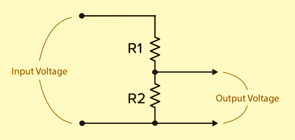
The pull-up resistor (R1) pulls the input node toward VDD. Inside the microcontroller, the input stage is essentially the gate of a MOSFET buffer. Its leakage path or effective input impedance (R2) is extremely large, often hundreds of kilo‑ohms to mega‑ohms. So, it provides almost no path to ground. Because R2 is so much larger than R1, almost no current flows through it, meaning it barely pulls the voltage down.
Since almost no current flows into the pin, the only real current path is:
VDD → Pull-up resistor → Input pin → (tiny leakage) → Ground
This behaves like a voltage divider, where:
- The pull-up resistor is the top resistor (to VDD)
- The input impedance is the bottom resistor (to GND)
But because the input impedance is very large, almost no voltage drops across it, so almost the entire voltage appears at the input pin.
The voltage at the input pin is:
Vpin=VDD × (Rinput/(Rpullup+Rinput))
Because Rinput ≫ Rpullup , the fraction becomes nearly 1, and the pin voltage becomes almost exactly VDD.
Let’s take an Example:
- Pull-up resistor: 10 kΩ (10000Ω)
- Input impedance: 1 MΩ( 1000000Ω)
- Supply: 9 V
Vpin = 9 × (1000000/(10000+ 1000000));
Vpin ≈ 8.9V
The pin sees 8.9 V, which is a strong, noise-free HIGH.
You can see, as a result, nearly the entire supply voltage appears at the input pin, and the microcontroller reads it as a clean, stable, and reliable HIGH level. This simple relationship is exactly why even a modest pull-up resistor can easily overcome the tiny leakage currents inside a digital input.
With this understanding, the design trade-off becomes very clear:
If the pull-up resistor is too small
- The pin returns HIGH very quickly.
- But you waste more current whenever an external device pulls the line LOW.
- (Because a small resistor lets more current flow to ground.)
If the pull-up resistor is too large
- Very little current is wasted.
- But the line becomes slow to rise (due to the MOSFET gate capacitance).
- And it becomes more sensitive to noise, especially in longer or noisy wires.
That is why engineers usually choose something in the middle, 4.7 kΩ to 47 kΩ, with 10 kΩ being a great general-purpose choice.
You May Also Like
- Does the Current Change After a Resistor?
- What is use of current Limiting Resistor?
- How to Interface an LED with an 8051 Microcontroller.
- Map-Based Method for GPIO Alternate Function Configuration.
- How to Interface an LED with an STM32H5.
- Interfacing of switch and led using the 8051.
- STM32 GPIO Guide: How to Control LEDs and Button.