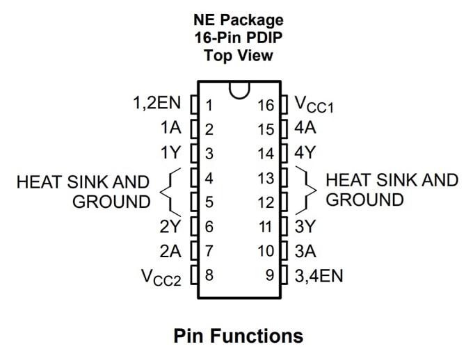
The L293D is a 16-pin dual H-bridge motor driver integrated circuit used to control DC motors and stepper motors with low-power control signals from a microcontroller.
It acts as a bridge between a microcontroller and your motors. Since microcontrollers operate on low voltage and cannot supply enough current to run a motor directly, the L293D sits in the middle. It takes low-power commands from the MCU and uses an external power source to drive the motors, allowing you to control both speed and direction (forward/reverse) safely.
In this tutorial, you will learn:
- What the L293D Motor Driver IC is and how it works
- The pin configuration and internal architecture of L293D
- How to interface L293D with a microcontroller
- How to control two DC motors (forward, reverse, stop, and speed control basics)
By the end of this article, you will be able to use the L293D motor driver in your robotics and embedded DIY projects 😊.
What is L293D Motor Driver IC?
The L293D is a popular dual H-bridge motor driver IC used to control DC motors using microcontrollers (such as 8051, Arduino, STM32, PIC, and Raspberry Pi). It acts as a bridge between low-power control signals from a microcontroller and high-power motor loads, enabling safe and reliable motor control.
Microcontroller GPIO pins cannot directly drive motors because motors require higher current and voltage. It solves this problem by providing current amplification and electrical isolation, making it ideal for motor-based embedded applications.
Key Features of L293D:
- Dual H-Bridge → controls 2 DC motors independently
- Motor supply voltage (Vs): 4.5 V to 36 V
- Logic supply voltage (Vss): 4.5 V to 7 V
- Max current: 600 mA per channel (peak ~1.2 A)
- PeakOutput current 1.2 A Per Channel.
- Built-in flyback diodes (this is the big advantage over L293)
- Thermal shutdown protection.
- Internal ESD Protection.

| Input A | Enable (EN) | Output (Y) | Description |
|---|---|---|---|
| High (H) | High (H) | High (H) | Output follows input A |
| Low (L) | High (H) | Low (L) | Output follows input A |
| Don’t Care (X) | Low (L) | High-Z (Z) | Output disabled (High Impedance) |
Why Do We Use L293D?
Microcontroller GPIO pins (like those on an Arduino, 8051, or STM32) can typically supply only a few milliamps of current at logic voltages (3.3V or 5V). In contrast, a DC motor requires significantly higher current and often a higher operating voltage to rotate effectively.
If you connect a motor directly to a microcontroller pin:
- The motor will fail: It likely won not receive enough current to spin.
- The pin may burn out: The current draw can overheat and permanently damage the pin.
- The MCU may crash: Electrical noise and back-EMF voltage spikes from the motor can reset or destroy the processor.
Now you may be wondering how to solve this problem. Do not worry, there is a simple and effective solution: the L293D motor driver IC.
The L293D motor driver solves these issues by acting as a high-current buffer between the microcontroller and the motor. It accepts low-power logic signals from the microcontroller to switch the higher currents required by the motors. Its internal H-bridge architecture and built-in diode protection enable safe, bidirectional motor control without complex external circuitry.
What the L293D Actually Does:
The following things L293D does that isist you to use th l293d with the DC motor.
1. Current Amplification:
Microcontroller GPIO pins can only source or sink a few milliamps of current, which is far too little to drive a DC motor. The L293D bridges this gap.
It takes low-power logic signals from your controller and uses them to switch high-current power to the motor, handling up to 600 mA per channel with supply voltages as high as 36 V. Essentially, it isolates the sensitive microcontroller circuitry while enabling the high-power switching required for mechanical motion.
2. Direction & Speed Control Using H-Bridge Circuits
The real power of the L293D is its internal dual H-bridge architecture. It contains two full H-bridges, allowing it to control two DC motors independently.
Bidirectional Motor Control: An H-bridge allows the voltage polarity across the motor terminals to be reversed electronically. By simply changing the logic levels on the input pins, you can: An H-bridge lets you change the direction of current flowing through the motor. By changing the logic levels (HIGH and LOW signals) on the input pins, you can make the motor rotate forward or backward.
- Rotate the motor Forward.
- Rotate the motor Backward.
- Break the motor for a quick stop.
- Let the motor coast to a natural stop
Without a motor driver like the L293D, you would need many extra transistors or relays, which makes the circuit bigger, more complicated, and harder to build.
Speed Control Using PWM: Each motor channel on the L293D has a dedicated Enable pin. By applying a PWM (Pulse Width Modulation) signal from your microcontroller to this pin, you can control the motor speed precisely.
- Higher Duty Cycle: Faster rotation (more average voltage).
- Lower Duty Cycle: Slower rotation (less average voltage).
This technique allows for smooth acceleration and deceleration, rather than just simple ON/OFF toggling.
Example: You can think of PWM like quickly turning a switch ON and OFF:
- If the switch is ON most of the time, the motor gets more power → it spins fast
- If the switch is ON only for short moments, the motor gets less power → it spins slowly
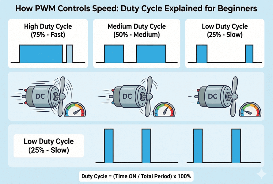
Even though the switch is toggling rapidly, the motor feels it as smooth speed control.
How an H-Bridge Works: Step-by-Step Explanation
An H-bridge is an electronic circuit that allows a DC motor to rotate in both directions by controlling the direction of current flow through the motor. It consists of four electronic switches (transistors) arranged in an “H” configuration.
Let’s break down its operation into three main states.
1. Neutral (OFF) State:
In the neutral state, all four switches are turned OFF.
- There is no complete electrical path between the power supply (+Vcc) and ground (GND).
- Since no current flows through the motor, it remains unpowered.
Result: The motor is unpowered and stationary. This is used when you want the motor to stop naturally without active braking.
2. Forward Rotation:
To rotate the motor clockwise, we activate two diagonal switches: S1 (top-left) and S4 (bottom-right).
Current Flow: Current leaves +Vcc, passes through S1, flows through the motor ((Left -> Right)), and returns to GND via S4.
Result: This specific direction of current creates a magnetic field that spins the motor shaft clockwise.
3. Reverse Rotation:
To reverse direction, we swap to the opposite diagonal pair: S2 (top-right) and S3 (bottom-left).
Current Flow: Current leaves +Vcc, passes through S2, flows through the motor (Right -> Left), and returns to GND via S3.
Result: Reversing the current flips the magnetic field, forcing the motor to spin counterclockwise.
| EN (Enable) | IN1 (1A / 3A) | IN2 (2A / 4A) | Motor Action | Explanation |
|---|---|---|---|---|
| HIGH | HIGH | LOW | Forward | OUT1 = HIGH, OUT2 = LOW. Current flows through the motor in one direction, so it spins forward. |
| HIGH | LOW | HIGH | Reverse | OUT1 = LOW, OUT2 = HIGH. Current direction is reversed, so the motor spins backward. |
| HIGH | LOW | LOW | Stop (Coast) | Both outputs LOW. Motor is not powered and slows down naturally (free running). |
| HIGH | HIGH | HIGH | Brake | Both outputs HIGH. Motor terminals are shorted internally, so it stops quickly. |
| LOW | X | X | Motor OFF | Enable pin is LOW. Outputs are in high-impedance state, motor is completely OFF. |
Why Does the L293D Get Extremely Hot?
It is very common for the L293D motor driver IC to become hot during operation. This usually does not mean the IC is faulty. Instead, the heating happens because of how the chip is designed and how it handles motor current. In simple language, the L293D wastes some electrical power as heat, especially when driving motors.
1. High Internal Voltage Drop:
The L293D uses bipolar junction transistors (BJTs) in its output stage instead of MOSFETs. These transistors waste more voltage as heat compared to modern motor drivers.
When current flows through the L293D:
- Each internal transistor drops about 1.2 to 1.8 volts typically.
- In an H-bridge configuration, to run a motor in one direction, current must pass through two transistors. So, the motor loses about:
1.2 V + 1.2 V ≈ 2.4 V   (minimum)

1.8 V + 1.8 V ≈ 3.6 V   (maximum)
- Lost voltage is converted directly into heat inside the IC because power loss depends on both voltage loss and current, as shown below:
Power Loss (P) = Voltage Drop × Current

P ≈ 2.5V×0.6A ≈ 1.5W
Dissipating 1.5 watts of heat inside a tiny plastic IC package, without any heat sink or active cooling, causes the temperature to rise very quickly. This is why the L293D often feels hot to the touch during operation.
2. Motor Stall or Overload Current:
DC motors are inductive loads that draw significantly more current when they are starting up or struggling to turn.
- When a motor starts, it pulls more current than usual
- When the motor gets stuck (called stall), current increases even more
A motor that is rated for 300 mA (normally uses 300 mA) during normal operation can suddenly draw more than 1 ampere when it starts or if the shaft gets stuck. This sudden current surge exceeds the L293D’s continuous current rating of 600 mA.
The L293D can survive short bursts like this, but if the motor starts often or carries a heavy load, the chip gets hot very quickly. Too much heat can make it shut down or get damaged.
3. Poor Heat Dissipation Capability
The L293D is a small plastic chip and does not have a heat sink. It releases heat mainly through its ground pins into the PCB. When it is used on a breadboard or a PCB with thin copper tracks, the heat cannot escape easily. Because of this, the heat stays trapped inside the chip, causing the temperature to rise very quickly.
4. Continuous Operation Near Maximum Ratings:
The datasheet says the chip can handle 600 mA per channel, but this is only the maximum limit, not what you should use all the time. If you run the chip at 600 mA continuously, it will heat up very fast. Too much heat can reduce its life or even damage it.
For beginners, and especially when there is no fan or heatsink, it is safer to keep the current below 400–500 mA. This helps the chip stay cool and work properly for a long time.
Typical Applications
- Line-following robots.
- Small robotic cars
- Stepper motor control
- Relay driving
- Educational projects (Arduino / STM32 / 8051)