In this “Arduino traffic light project”, you will design and implement a working traffic light system using LEDs and Arduino code. In this project, you will learn how Arduino digital pins operate, how to control output devices, and how to write a non-blocking code, and how to write timing logic that mimics real-world traffic signal behavior.
This project is ideal for beginners who want to build practical electronics skills with Arduino.
In this tutorial, you will learn how to write Arduino firmware to control a traffic light system. By the end of this tutorial, you will learn:
- How to write scalable and responsive Arduino code.
- How to manage multiple software timers in a single loop()
- How to program Arduino to control RGB traffic light module without using delay() function
- How to write logic for Traffic Lights signal.
- How to program Arduino to control RGB traffic light module
- How to connect multiple LEDs to Arduino.
What Does This Project Do?
In this Arduino traffic light project, we create a simple traffic light using an Arduino board and three LEDs. The LEDs represent red, yellow (amber), and green lights. They are connected to the Arduino, which runs a program to turn each LED on and off in sequence, just like a real traffic signal on the road.
How Arduino traffic light project Works:
The Arduino controls three LEDs and turns them ON one by one just like the real traffic lights work.
🔴 Red Light (STOP):
- The red LED turns ON first.
- It stays ON for a fixed amount of time, telling vehicles to stop.
🟡 Yellow/Amber (GET READY):
- After the red light turns OFF, the yellow LED turns ON for a short time.
- This acts as a warning that the signal is about to change.
🟢 Green Light (GO):
- Next, the green LED turns ON.
- This means vehicles are allowed to move.
Once the green light finishes, the Arduino starts the same sequence again from the red light. This same sequence in loop makes the traffic light signal system.
Components Required:
To blink an LED using Arduino, you need the following components:
| Component | Quantity |
|---|---|
| Arduino board (Uno / Nano / Mega) | 1 |
| LED (Red, Green, Yellow) | 3 |
| Resistor (220Ω or 330Ω) | 3 |
| Breadboard | 1 |
| Jumper wires | As required |
| USB cable | 1 |
Circuit Diagram Explanation:
To keep this tutorial simple and beginner friendly. I will follow a clear step-by-step wiring approach.
In this setup, each LED is connected to a different Arduino digital pin using a current-limiting resistor to prevent damage from excessive current.
LED to Arduino Pin Mapping:
| LED | Arduino Pin | Purpose |
|---|---|---|
| LED 1 | Pin 11 | Blink / Output Indicator |
| LED 2 | Pin 12 | Blink / Output Indicator |
| LED 3 | Pin 13 | Blink / Output Indicator |
Step-by-Step Wiring:
Follow these simple steps to connect an LED to your Arduino board safely.
Step 1: Insert the LEDs into the breadboard
Make sure each LED is placed in a separate row.
Step 2: Identify LED terminals
- Long leg → Anode (+)
- Short leg → Cathode (–)
Step 3: Connect current-limiting resistors
Attach a 220Ω resistor to the anode (long leg) of each LED.
Step 4: Connect resistors to Arduino pins
- LED 1 → Pin 10
- LED 2 → Pin 11
- LED 3 → Pin 12
Step 5: Connect all cathodes to ground
- Join all short legs (cathodes) of the LEDs.
- Connect them to the GND pin of the Arduino.
Traffic Lights Arduino Code:
Let’s see to How to Program for Traffic Light module. Open the Arduino IDE, write the following code, and upload the sketch to your Arduino board to create a simple traffic light system.
/*
 * Created by Aticleworld.com
 *
 * Tutorial page:
 * https://aticleworld.com/arduino-traffic-light
 */

const int red = 11;
const int yellow = 12;
const int green = 13;

/**
 * @brief Arduino setup function
 *
 * This function runs once when the Arduino starts.
 * It configures the LED pins as output.
 */
void setup()
{
  pinMode(red, OUTPUT); ///< Configure red LED pin as output
  pinMode(yellow, OUTPUT); ///< Configure yellow LED pin as output
  pinMode(green, OUTPUT); ///< Configure green LED pin as output
}

/**
 * @brief Arduino main loop function
 *
 * This function runs continuously after setup().
 * It turns ON each LED in sequence to mimic
 * a real traffic light system.
 */
void loop()
{
  digitalWrite(green, HIGH); ///< Turn Green LED ON
  delay(8000); ///< Keep Green ON for 8 seconds
  digitalWrite(green, LOW); ///< Turn Green LED OFF

  digitalWrite(yellow, HIGH); ///< Turn Yellow LED ON
  delay(1000); ///< Keep Yellow ON for 1 seconds
  digitalWrite(yellow, LOW); ///< Turn Yellow LED OFF

  digitalWrite(red, HIGH); ///< Turn Red LED ON
  delay(8000); ///< Keep Red ON for 8 seconds
  digitalWrite(red, LOW); ///< Turn Red LED OFF

  digitalWrite(yellow, HIGH); ///< Turn Yellow LED ON
  delay(1000); ///< Keep Yellow ON for 1 seconds
  digitalWrite(yellow, LOW); ///< Turn Yellow LED OFF
}
How the Code Works:
- Each LED pin is configured as an OUTPUT using pinMode()
- digitalWrite() turns LEDs ON (HIGH) or OFF (LOW)
- delay() controls how long each light stays ON
- The loop() function keeps the sequence running repeatedly
- This is a great introduction to sequential control using a microcontroller.
Optimized Arduino Traffic Light Control Code:
The above traffic light code is helpful for understanding the basic behavior, but it is not scalable. Here, we implement a scalable Arduino firmware to control the traffic light. This version efficiently manages the red, yellow, and green LED using improved logic, resulting in smooth and reliable operation.
/*
 * Created by Aticleworld.com
 *
 * Tutorial page: https://aticleworld.com/Arduino-traffic-light
 */
/*==========================================================
 * State Definitions
 *==========================================================*/
enum TrafficState {
  STATE_GREEN,
  STATE_YELLOW_AFTER_GREEN,
  STATE_RED,
  STATE_YELLOW_AFTER_RED
};

/*==========================================================
 * Function Prototypes
 *==========================================================*/
void changeState(TrafficState newState);

/*==========================================================
 * Configuration
 *==========================================================*/
// LED pin assignments
const uint8_t PIN_LED_RED = 11;
const uint8_t PIN_LED_YELLOW = 12;
const uint8_t PIN_LED_GREEN = 13;

// Timing constants (milliseconds)
const unsigned long DURATION_GREEN = 8000;
const unsigned long DURATION_YELLOW = 1000;
const unsigned long DURATION_RED = 8000;

/*==========================================================
 * Global Variables
 *==========================================================*/
TrafficState currentState = STATE_GREEN;
unsigned long lastStateChangeTime = 0;

/*==========================================================
 * Helper Functions
 *==========================================================*/

/**
 * @brief Changes traffic light state
 * Handles exit actions of old state and
 * entry actions of new state
 */
void changeState(TrafficState newState)
{
  /* ---------- Exit Logic ---------- */
  switch (currentState) {
  case STATE_GREEN:
    digitalWrite(PIN_LED_GREEN, LOW);
    break;

  case STATE_YELLOW_AFTER_GREEN:
    digitalWrite(PIN_LED_YELLOW, LOW);
    break;

  case STATE_RED:
    digitalWrite(PIN_LED_RED, LOW);
    break;

  case STATE_YELLOW_AFTER_RED:
    digitalWrite(PIN_LED_YELLOW, LOW);
    break;
  }

  /* ---------- Update State ---------- */
  currentState = newState;
  lastStateChangeTime = millis();

  /* ---------- Entry Logic ---------- */
  switch (currentState) {
  case STATE_GREEN:
    digitalWrite(PIN_LED_GREEN, HIGH);
    break;

  case STATE_YELLOW_AFTER_GREEN:
    digitalWrite(PIN_LED_YELLOW, HIGH);
    break;

  case STATE_RED:
    digitalWrite(PIN_LED_RED, HIGH);
    break;

  case STATE_YELLOW_AFTER_RED:
    digitalWrite(PIN_LED_YELLOW, HIGH);
    break;
  }
}

/*==========================================================
 * Arduino Setup
 *==========================================================*/
void setup()
{
  pinMode(PIN_LED_RED, OUTPUT);
  pinMode(PIN_LED_YELLOW, OUTPUT);
  pinMode(PIN_LED_GREEN, OUTPUT);

  // Ensure safe startup state
  digitalWrite(PIN_LED_RED, LOW);
  digitalWrite(PIN_LED_YELLOW, LOW);
  digitalWrite(PIN_LED_GREEN, HIGH);

  currentState = STATE_GREEN;
  lastStateChangeTime = millis();
}

/*==========================================================
 * Arduino Main Loop (Non-Blocking)
 *==========================================================*/
void loop()
{
  const unsigned long currentTime = millis();
  const unsigned long timeInState = currentTime - lastStateChangeTime;

  switch (currentState) {
  case STATE_GREEN:
    if (timeInState >= DURATION_GREEN) {
      changeState(STATE_YELLOW_AFTER_GREEN);
    }
    break;

  case STATE_YELLOW_AFTER_GREEN:
    if (timeInState >= DURATION_YELLOW) {
      changeState(STATE_RED);
    }
    break;

  case STATE_RED:
    if (timeInState >= DURATION_RED) {
      changeState(STATE_YELLOW_AFTER_RED);
    }
    break;

  case STATE_YELLOW_AFTER_RED:
    if (timeInState >= DURATION_YELLOW) {
      changeState(STATE_GREEN);
    }
    break;
  }
}
How This Code Works:
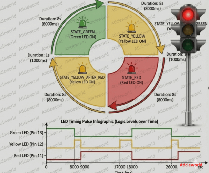
This program uses a Finite State Machine (FSM) approach to control the traffic lights. Finite State Machine (FSM) is a common and reliable design technique in embedded systems.
This code has four well-defined states:
- Green – Vehicles are allowed to move.
- Yellow (after Green) – Signal is about to turn Red.
- Red – Vehicles must stop.
- Yellow (after Red) – Signal is about to turn Green.
Each state represents which LED should be ON and how long it should stay ON.
Key Functions Explained:
Let’s look at the most important functions used in this Arduino traffic light code and understand their role.
changeState():
This function is responsible for handling state transitions in the traffic light system. It first turns OFF the LED of the previous state, updates the system to the newState, and then turns ON the correct LED.
What it does:
- Turns OFF the LED of the current state.
- Updates the system to the new state.
- Turns ON the LED corresponding to the new state.
- Resets the timer using millis() to track the next transition.
Because we manage all state changes in this function, it makes the code cleaner, more readable, and easier to maintain.
loop():
The loop() function runs continuously and checks the time using millis(). Once the time in the current state exceeds the defined duration, it triggers a switch to the next state.
What it does:
- It checks the elapsed time using millis()
- When the active state exceeds its predefined duration, the program switches to the next state
- No delay() is used, making the system non-blocking and efficient
Uploading the Program:
Once your code is ready, follow these steps to upload it to the ATmega2560 (Arduino Mega 2560):
Connect the Board:
Plug your Arduino Mega 2560 into your computer using a USB cable.
Open the Arduino IDE:
Launch the Arduino IDE on your PC or laptop.
Select the Board:
Go to Tools → Board → Arduino AVR Boards and select Arduino Mega or Mega 2560.

Select the Port:
Go to Tools → Port and choose the port that appears after connecting the board (for example, COM4 on Windows or /dev/tty… on macOS/Linux).
Upload the Code:
Click the Upload button (right-arrow icon) or press Ctrl + U.

After the upload is complete, the built-in LED will start blinking according to your program.
Frequently Asked Questions (FAQs):
Q-1) What is the purpose of a traffic light project?
It helps students understand how traffic light control systems work and introduces basic electronics and Arduino programming concepts.
Q-2) Can I build a traffic light signal project without an Arduino?
Yes, you can build a basic traffic light system using timer ICs or simple logic circuits, but Arduino makes it more flexible and easier to modify.
Q-3) What components are used in a traffic light Arduino project?
Common components include LEDs (red, yellow, green), resistors, jumper wires, a breadboard, an Arduino board, and a power source.
Q-4) Is this project suitable for beginners?
Yes! This is an excellent beginner project for learning Arduino basics, LED control, and timing logic.
Q-5) Can I change the timing of the traffic lights?
Yes, you can easily change the delay values in the Arduino code to control how long each light stays ON.
Q-6) What skills will I learn from this project?
You will learn basic circuit wiring, Arduino programming, digital output control, and real-world system simulation.
You May Also Like
- Blink Multiple LEDs at Different Speeds Using Arduino.
- Arduino Blink LED Tutorial – Circuit and Code Example.
- How To Control An LED With A Button and Arduino.
- Does the Current Change After a Resistor?
- What is use of current Limiting Resistor?
- How to Interface an LED with an 8051 Microcontroller.
- Map-Based Method for GPIO Alternate Function Configuration.
- How to Interface an LED with an STM32H5.
- Interfacing of switch and led using the 8051.
- STM32 GPIO Guide: How to Control LEDs and Button.