In this tutorial, you will learn how to interface a DC motor with Arduino using a motor driver IC (L293D). DC motors are widely used in embedded systems for motion control applications such as robots, conveyor belts, automatic doors, and small automation projects.
Many beginners try to connect a DC motor directly to the GPIO pins of the Arduino. This is a common mistake. The Arduino cannot drive a DC motor directly because a motor requires a high current and more power to operate, while the microcontroller GPIO pins can supply only a few milliamps at 5V.
Also directly connecting a motor to the Arduino pins can not only prevent the motor from running properly but may also permanently damage the microcontroller. To safely control a DC motor, a motor driver IC like the L293D is required. It acts as an interface between the microcontroller and the motor, providing the necessary current and voltage while protecting the Arduino.
By the end of this article, you will learn:
- What a DC motor is.
- Why you cannot connect it directly to Arduino.
- how to interface a DC motor with Arduino using L293D.
- How to control speed and direction.
- A real step-by-step wiring diagram.
- Arduino code that actually works.
Components Required:
To run the DC motor using Arduino, you need the following components:
| Qty | Component | Type | Remarks |
|---|---|---|---|
| 1 | Arduino | Microcontroller Board | Main controller |
| 1 | DIY ables STEM V3 | Arduino Compatible | Alternative board |
| 1 | USB 2.0 Cable (Type A/B) | Cable | For USB-A PCs |
| 1 | USB 2.0 Cable (Type C/B) | Cable | For USB-C PCs |
| 1 | L2D39 Motor Driver Module | Motor Driver | Controls DC motor direction |
| 1 | 5V DC Motor | Actuator | Rotational motion |
| 1 | 5V Power Adapter | Power Supply | Motor power source |
| 1 | DC Power Jack | Connector | External power input |
| 1 | Jumper Wires | Wiring | Interconnections |
| Optional | Arduino Shields & Enclosure | Accessories | Improves prototyping & safety |
How a DC Motor Works:
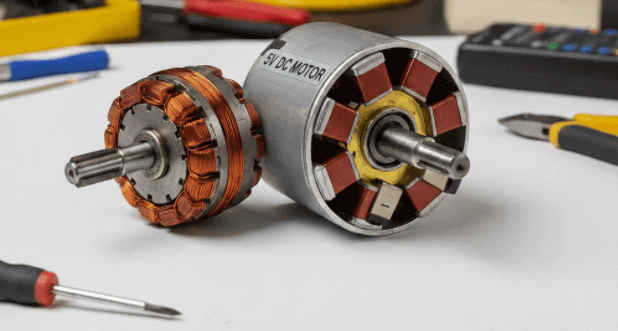
A DC motor is an electrical device that converts direct current (DC) electrical energy into mechanical rotational motion. It works by passing electric current through a coil placed inside a magnetic field.
When the current flows, it interacts with the magnetic field and creates a force that causes the coil and motor shaft to rotate. To keep the motor rotating continuously in one direction, a mechanical component called a commutator automatically reverses the current direction at the right time during rotation. This process happens internally, without any software control. As long as DC power is supplied, this cycle repeats and the motor keeps spinning.
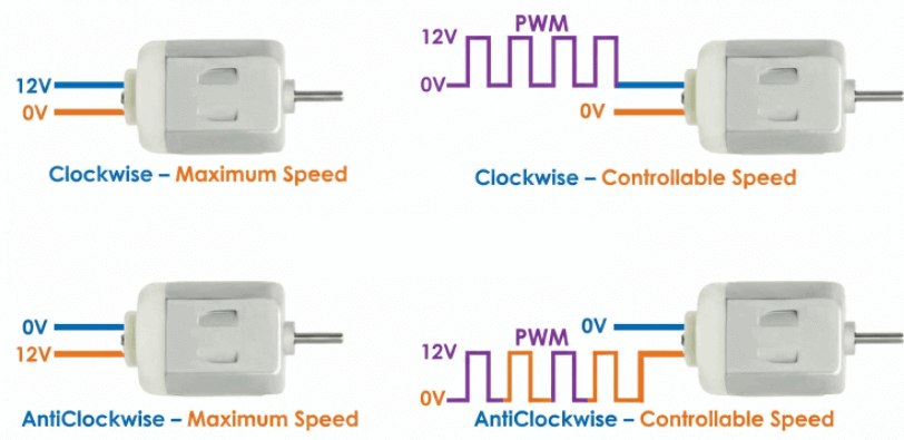
A DC motor has two terminals: positive (+) and negative (–). When a DC voltage is applied across these terminals, the motor starts rotating. If the polarity is reversed, the direction of rotation also reverses.
This behavior allows us to control two important things:
- Speed – how fast the motor rotates (controlled using PWM)
- Direction – clockwise or counter-clockwise rotation (controlled by changing polarity using an H-bridge)
Using Arduino along with a L293D (motor driver IC), we can easily control both the speed and direction of a DC motor.
Why You Must Not Connect a DC Motor Directly to Arduino:
One of the most dangerous mistakes beginners make is connecting a DC motor directly to Arduino GPIO pins.
This approach may seem convenient, but it is electrically unsafe and can easily result in permanent hardware damage to the Arduino board.
Reasons why This Can Destroy Your Arduino:
There are three specific reasons why this kills your microcontroller if you wire a motor directly to it.
1. The Current Overload (Current Limitation):
Think of an Arduino GPIO pin like a very small pipe designed to carry only a trickle of water.
The core problem when connecting a DC motor directly is a severe mismatch in current capability. An Arduino pin is designed to safely source or sink about 20 mA (the trickle), while even a small DC motor can demand 500 mA or more at startup. L
Arduino GPIO Limits:
- ATmega328P GPIO absolute maximum: 40 mA
- Recommended continuous current: 20 mA
DC Motor Requirements:
- Even a small toy DC motor typically draws 300–500 mA during normal operation.
- At startup, the current can be even higher.
What Actually Happens:
- The motor demands 10×–20× more current than the GPIO pin can supply.
- This excessive load forces the microcontroller’s internal output transistors to conduct far beyond their safe limits.
- The transistors overheat and fail, resulting in:
- A burnt GPIO pin, or.
- A permanently damaged microcontroller.
2. Stall Current Surge (Startup Surge)
A DC motor draws its highest current at startup or when stalled. At this moment, the motor behaves almost like a short circuit. This momentary surge called stall current. It is typically 5–10× higher than the normal running current and can easily reach 2A or more, even for small motors.
Such a sudden current spike instantly overloads the Arduino GPIO pin, damaging the internal output transistor before the motor completes its first rotation.
3. Back EMF (The “Electrical Kick”)
This is the silent killer that most beginners completely miss. A DC motor has coils of wire inside it. When the motor is running, these coils store energy in a magnetic field.
When you suddenly cut power to the motor, that magnetic field collapses quickly. This collapse creates a high-voltage reverse spike, called Back EMF (inductive kickback). This spike can rise far above the Arduino’s safe 5V level. It travels back through the wires and can damage or destroy the microcontroller’s internal logic and protection diodes. Without proper protection, such as flyback diodes or a motor driver IC, this damage is inevitable over time.
So, the question now is: how do we solve this problem?
Don’t worry, in the following section, we will explain the proper and safe approach to controlling a DC motor with Arduino.
How to Control a DC Motor Using Arduino:
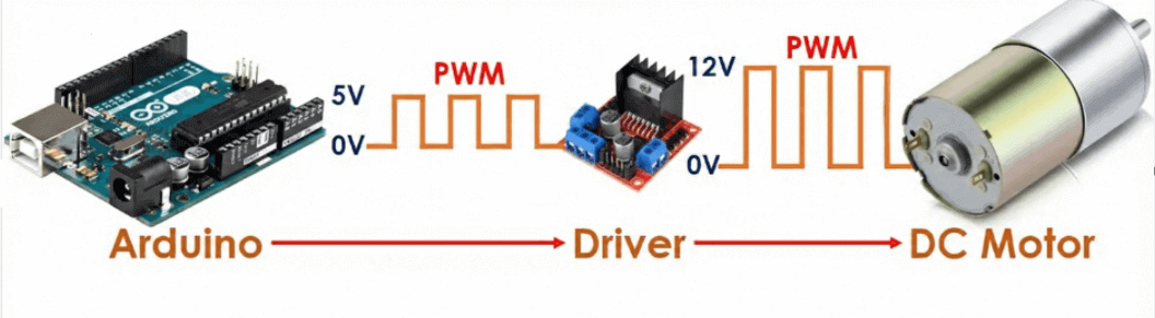
Controlling a DC motor using Arduino mainly involves two parameters: speed and direction. Arduino can generate a PWM (Pulse Width Modulation) signal, which is useful for speed control. However, the PWM signal from Arduino has low voltage and limited current, so it cannot drive a DC motor directly.
Arduino GPIO pins are designed only for logic-level signals, not for powering loads like motors. A typical Arduino pin can supply only 20–40 mA, while even a small DC motor may require hundreds of milliamps during startup (stall current). Directly connecting a DC motor to an Arduino pin can permanently damage the microcontroller.
That is why a motor driver ICs (H-bridge) such as L293D or L298N is required when connecting a DC motor to an Arduino. It safely controls a DC motor and act as a bridge between the Arduino and the motor.
A motor driver performs two key functions:
- Power Amplification: It takes the low-power PWM signal from the Arduino and uses an external power supply to drive the motor with the required higher voltage and current.
- Direction Control: It contains an H-bridge circuit that switches the polarity of the power supply, allowing the motor to rotate clockwise or counterclockwise.
How it Connects:
Controlling a DC motor mainly involves two important factors: speed and direction. Let’s see how each of these can be controlled.
Direction Pins:
Connect two digital pins from the Arduino to the motor driver inputs. These pins control the direction of motor rotation by changing the polarity applied to the motor.
Speed Pin:
Connect one PWM pin from the Arduino to the Motor driver Enable pin. This pin controls the motor speed using PWM.
Power:
The motor driver must be powered using an external power supply to safely deliver high current to the DC motor. The Arduino is used only to generate low-power control signals such as direction and PWM.
Motor Control Logic:
We can control a DC motor using Arduino in two main aspects:
1. Direction Control:
The Arduino controls the direction of rotation by setting logic levels on the two direction pins of the motor driver:
By switching these logic levels, the motor driver reverses the polarity across the motor terminals.
Direction Note:
2. Speed Control:
To control motor speed, the Arduino sends a PWM (Pulse Width Modulation) signal to the Enable pin of the motor driver.
- Higher PWM duty cycle –> Higher motor speed
- Lower PWM duty cycle –> Lower motor speed
In Arduino programming (using analogWrite), PWM values range from 0 to 255:
- 0 –> Motor stopped
- 255 –> Motor runs at maximum speed
The motor driver takes this low-power signal from the Arduino and uses it to control how much power from the external supply goes to the motor, which changes the motor’s speed.
How to Stop a DC Motor
A DC motor can be stopped in two ways, depending on how quickly you need it to halt:
1. Coasting (Gradual Stop)
Method: Set the PWM value to 0 on the Enable pin (ENA/ENB).
Result: The motor loses power and slows down naturally due to friction and inertia. This method does NOT actively stop the motor; it simply removes the drive voltage. This approach is smoother but takes longer to come to a complete stop.
2. Braking (Rapid Stop)
Method: Set both direction pins to the same logic level (both HIGH or both LOW).
Result: This electronically shorts the motor terminals through the H-bridge, creating a braking effect that forces the motor to stop almost instantly. This is useful for precise positioning, fast response systems, or emergency stops.
Wiring Arduino with L293D IC
Place the L293D IC on a breadboard with the notch facing upward. This orientation is important for correct pin identification.
1. Power Connections:
The L293D requires two separate power supplies to operate safely and correctly:
- Pin 16 (VCC1):
Connect to Arduino 5V.
(This powers the internal logic of the IC only.) - Pin 8 (VCC2):
Connect to external battery positive (+).
(This supplies high current and voltage to the motor.) - GND Pins (4, 5, 12, 13):
Connect to external battery negative (−) AND Arduino GND.
All grounds must be common for proper operation.
2. Control Connections:
Use the following connections to interface the motor and Arduino:
⚠️ Very Important Warning
- Do NOT confuse Pin 8 and Pin 16 of the L293D IC.
- Pin 16 must ALWAYS be connected to 5V only (Arduino 5V).
- Connecting the high-voltage motor supply to Pin 16 will permanently damage the L293D IC.
- Pin 8 is the ONLY pin intended for motor supply voltage (VCC2).
Best Practice: Add a decoupling capacitor (100nF or 0.1µF) close to the motor terminals to reduce electrical noise and protect the Arduino from voltage spikes.
Arduino Code Example:
Here is a simple Arduino sketch to control a DC motor’s speed and direction using an L293D or L298N motor driver module.
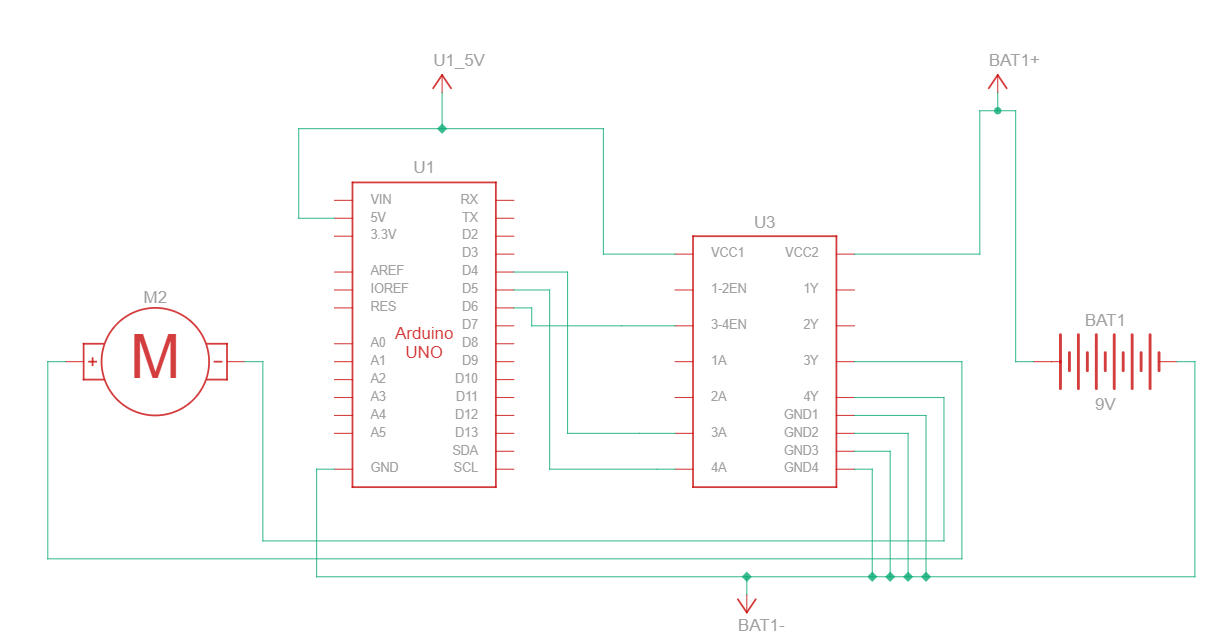
Circuit Connections for This Code
- 3A (Direction Pin 1): Digital Pin 4
- 4A (Direction Pin 2): Digital Pin 5
- EN (Speed / PWM Pin): Digital Pin 6 (Must be a PWM-enabled pin)
// Define Motor Control Pins
const int motorPin1 = 4;   // IN1
const int motorPin2 = 5;   // IN2
const int enablePin = 6;  // EN (PWM pin)

void setup()
{
  pinMode(motorPin1, OUTPUT);
  pinMode(motorPin2, OUTPUT);
  pinMode(enablePin, OUTPUT);

  // Serial monitor
  Serial.begin(9600);
}

void loop()
{
  // 1. Move Forward at full speed
  Serial.println("Moving Forward");
  moveMotor(true, 255);
  delay(10000);

  // 2. Stop the motor
  Serial.println("Stopping");
  stopMotor();
  delay(2000);

  // 3. Move Backward at full speed
  Serial.println("Moving Backward");
  moveMotor(false, 255);
  delay(10000);

  // 4. Stop again
  Serial.println("Stopping");
  stopMotor();
  delay(2000);
}


// direction: true = forward, false = backward
// speed: 0 to 255
void moveMotor(bool direction, int speed)
{
  speed = constrain(speed, 0, 255); // Safety clamp**

  if (direction)
  {
    digitalWrite(motorPin1, LOW);
    digitalWrite(motorPin2, HIGH);
  }
  else
  {
    digitalWrite(motorPin1, HIGH);
    digitalWrite(motorPin2, LOW);
  }

  analogWrite(enablePin, speed);
}

// Stop the motor (coast stop)
void stopMotor()
{
  digitalWrite(motorPin1, LOW);
  digitalWrite(motorPin2, LOW);
  analogWrite(enablePin, 0);
}
You May Also Like
- L293D Motor Driver IC: Pinout, Applications, and Circuits
- Learn Arduino Button Piezo Buzzer.
- How To Control An LED With A Button and Arduino.
- Learn Arduino Button Relay.
- Arduino Blink LED Tutorial – Circuit and Code Example.
- Multiple Blinking LED on Arduino.
- Does the Current Change After a Resistor?