Have you ever wanted to make your own electronic circuit but felt confused by all those wires, soldering irons, and complex circuit diagrams?
Good news — you don’t need to solder anything to start learning electronics!
All you need is a breadboard — a simple tool that lets you build and test circuits easily, without any permanent wiring.
In this beginner blog post, you will learn:
- What a breadboard is and how it actually works
- How to connect electronic parts the right way
- Common mistakes beginners make (and how to avoid them)
- Some fun and easy circuits you can try right away
Whether you are a student, a hobbyist, or just someone curious about how electronics work — this guide will help you get started in no time.
By the end, you will build your first LED circuit and understand how electricity flows through it. The good news is 😊 you can do it all without picking up a soldering iron!
What Is a Breadboard and Why Do You Need One?
A breadboard is a simple tool that helps you build and test electronic circuits without using a soldering iron.
It lets you plug in components like resistors, LEDs, or sensors and connect them with jumper wires, just like drawing a circuit diagram in real life.

Now you might be wondering, why is it called a breadboard?
Well, let’s go back in time for a moment.
Before modern plastic breadboards existed, engineers actually used wooden cutting boards — the same kind used to slice bread! They hammered small nails into the board and wrapped wires around them to make connections. And that is how the name “breadboard” was born.
Today’s breadboards are made of plastic, reusable, and completely safe to use. They are perfect for students, hobbyists, and even professionals who want to quickly build and test their electronic ideas.
Understanding Breadboard Layout:
A breadboard might look like a maze of holes at first glance, but once you understand its layout, you will see how simple and smart its design really is.
The breadboard has hidden internal connections that link certain holes together — some run vertically, and others horizontally, depending on which part of the board you’re using.
Typically, the outer columns (called power rails) are used to distribute power across the board — one for positive voltage and the other for ground.
Meanwhile, the inner rows (known as terminal strips) are where you insert and connect components to build your circuit.
Let’s break it down section by section 👇

1. Power Rails (Outer Columns):
It is common practice to use the outer columns on both sides of the breadboard to connect your power supply. These columns are called power rails. They are connected vertically, meaning all the holes in a single column share the same electrical connection.
So, if you connect +5V to the top hole of the red-marked column, every hole below it in that column will also carry +5V. The same goes for the blue (or black) column, which is used for ground (GND).
So, if you connect +5V to the top hole of the red-marked column, every hole below it in that column will also have +5V, because all those points are connected inside the breadboard.
But remember, many breadboards have a small gap in the middle of the power rail. That means the power doesn’t continue past that break unless you bridge it with a jumper wire. The same thing goes for the blue or black column, which is usually used for ground (GND).
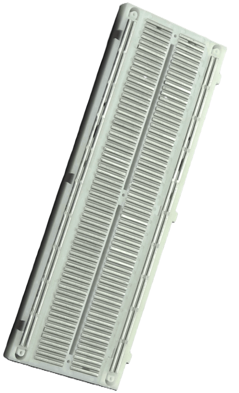
You can actually see the inside view of a breadboard, where metal strips act like tiny conductors, connecting the holes together in a row or column. When you insert a component lead or a jumper wire into any hole, it makes contact with a metal clip hidden underneath — and that’s how electric current flows between the connected points.
In the power rails, these metal strips run horizontally along the sides of the board, allowing power and ground to reach different parts of your circuit easily.
👉 Always remember:
- Red Line → Positive (+VCC)
- Blue/Black Line → Negative (Ground or 0V)
This simple convention helps keep your circuit neat and reduces confusion when troubleshooting connections later.

2. Terminal Strips (Middle Part):
The middle part of the breadboard is where you put your electronic parts like resistors, LEDs, and ICs. This section is divided into two halves by a small gap in the center.
- Each half has columns of 5 holes labeled A–E on one side and F–J on the other.
- All 5 holes in one column are connected together inside the breadboard.
- The gap in the middle separates both sides — they are not connected to each other.
This gap is very useful because you can easily place IC chips (like timers or logic ICs) across it — one row of pins goes on the left side, and the other on the right side. That way, each pin has its own separate connection point for adding other components or wires. Consider below image for better understanding.

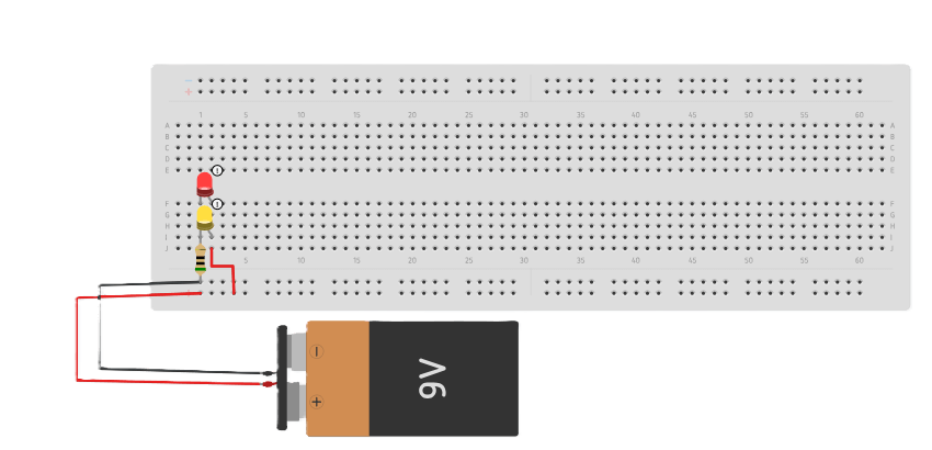
Example Breadboard Circuit:
Let’s put this knowledge into action! It is time to build your first LED circuit and see how a breadboard actually works in practice.
Components:
- Breadboard.
- LED (any color)
- Resistor (220Ω to 330Ω)
- Jumper wires
- Power source (5V or 9V battery)
Steps:
1. Insert the LED:
- Place the long leg (anode) in one row.
- Place the short leg (cathode) in another row.
2. Add a Resistor:
- Connect one end of the resistor to the LED’s cathode (short leg).
- The other end goes to GND.
3. Wire the Power Rails:
- Connect 5V (or battery +) to the red rail.
- Connect GND (or battery –) to the blue rail.
4. Complete the Circuit:
- Use a jumper wire to connect the LED anode to the 5V rail.
5. Power On:
- The LED should glow!
- If not, check polarity and resistor placement.
Best Wire Type for Breadboards:
When working with a breadboard, the type of wire you choose makes a big difference in how reliable your connections are. In my experience, it is best to use 22–23 AWG single-strand (solid-core) wires. These wires fit snugly into the breadboard holes, ensure firm electrical contact, and are easy to insert and remove without damaging or loosening the metal clips inside.
Also, it is my recommendation not to use the following types of wires:
- Stranded wires: They are too flexible and often make poor or intermittent contact, which can cause your circuit to behave unpredictably.
- Thick component leads: These can stretch or damage the delicate metal clips inside the breadboard, making future connections loose or unreliable.
So, stick with solid-core wires — your breadboard will last much longer, and your circuits will work more reliably.
Common Breadboard Mistakes and Tips:
There are a few common mistakes and helpful tips you should know — they will make your breadboard projects easier, cleaner, and more reliable.
Mistakes:
1. Ignoring the center gap:
If both legs of a component sit on the same side, they are shorted. Always use the gap to isolate connections.
2. Unlinked power rails:
Top and bottom rails are not always connected. Bridge them with jumpers to ensure proper power distribution.
3. Loose or old breadboards:
Loose holes cause unstable connections. Replace the breadboard if signals flicker or components misbehave.
4. Messy wiring:
Crossed, long wires create confusion. Keep wiring short, neat, and color-coded.
4. No decoupling capacitors:
Always place a 0.1 µF capacitor near each IC’s power pins for clean, stable operation.
Tips:
1. Plan before you build:
Think about where each part will go before plugging anything in. It makes your circuit neat and easier to fix later.
2. Use color-coded wires:
Use red for power, black for ground, and other colors for signals. This helps you spot mistakes quickly.
3. Keep wires short and tidy:
Short, flat wires not only look clean but also reduce noise and connection issues.
4. Check connections with a multimeter:
Before turning on power, make sure everything is connected correctly — this can save your components.
5. Organize your circuit:
If your project is big, group related parts together or mark sections with tape or labels.
Breadboard FAQs:
Q1: Can I reuse a breadboard for multiple projects?
Yes, absolutely! Breadboards are made for repeated use. Just remove the old components and you’re ready to build a new circuit.
Q2: Can I use a breadboard with Arduino or Raspberry Pi?
Definitely. Breadboards work perfectly with Arduino, Raspberry Pi, and other microcontrollers, making them ideal for beginners learning electronics and coding.
Q3: Do I need to solder anything?
No soldering needed! Breadboards are completely solderless, which means you can experiment freely without making permanent connections.
Q4: How much voltage and current can a breadboard handle?
Most breadboards can safely handle up to 5V (sometimes 12V) and less than 1A of current. Avoid using them for high-current or high-voltage circuits to prevent damage or heating.