In this article, we will guide you through the steps to create a simple project that blinks an LED connected to the STM32 microcontroller. For this tutorial, we’ll use the STM32 NUCLEO-H563ZI development board.
In this tutorial, we will take advantage of STM32CubeMX to generate the necessary code and utilize HAL functions for an efficient implementation. This project is an excellent starting point for beginners who are new to STM32 development or microcontroller programming in general.
Hardware Setup:
| Component Name | Quantity | Purchase Link |
|---|---|---|
| STM32 NUCLEO Development Board | 1 | Amazon |
| LED | 1 | Amazon |
| Resistor 220 ohm | 1 | Amazon |
| Breadboard | 1 | Amazon |
| Jumper wire pack | 1 | Amazon |
| USB Mini-B cable | 1 | Amazon |
For troubleshooting, some extremely useful test equipment
| Equipment Name | Purchase Link |
|---|---|
| Best Oscilloscope for Professionals | Amazon |
| Best Oscilloscope for Beginners and Students | Amazon |
| Logic Analyzer | Amazon |
| Best Budget Multimeter | Amazon |
| Adjustable Bench Power Supply | Amazon |
Affiliate Disclosure: Some links on this site are affiliate links. If you make a purchase, we may earn a small commission at no extra cost to you. Affiliates include Amazon.com and others.
Steps to generate Code to Blinking an LED on STM32:
In the below section, I will guide you step-by-step on how to generate code for blinking an LED on your STM32 board. By following these steps, you will learn how to use STM32CubeMX to configure the microcontroller’s pins, and how to write the corresponding code with STM32 HAL libraries.
Step: -1 Create Project Using STM32CubeMX:
Launch STM32CubeMX: Open the STM32CubeMX application on your system.
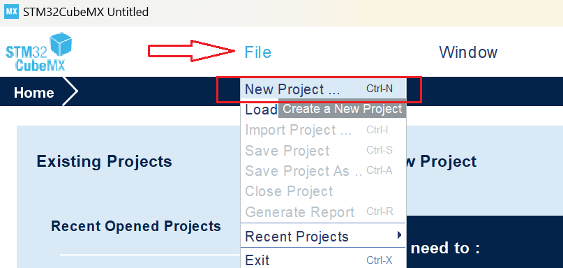
Create a New Project: Open STM32CubeMX and navigate to File > New Project > Create New Project.
Select Your Board OR MCU: Go to the Board Selector tab and enter the name of your STM32 development board. For this tutorial, we are using the NUCLEO-H563ZI board.
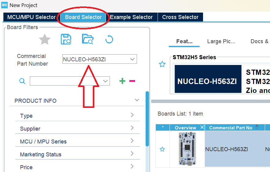
Click on Start Project and select without trustZone activated or with trustZone activated. I will select without trustZone activated here.

Step: -2 Pinout Configuration:
Navigate to the ‘Pinout & Configuration‘ tab in STM32CubeMX. Identify the GPIO pin connected to the LED based on your board’s documentation. For instance, on the STM32H6ZI board, the user yellow LED (LD2) is connected to PF4. In this example, we’ll configure PF4 as the LED pin.
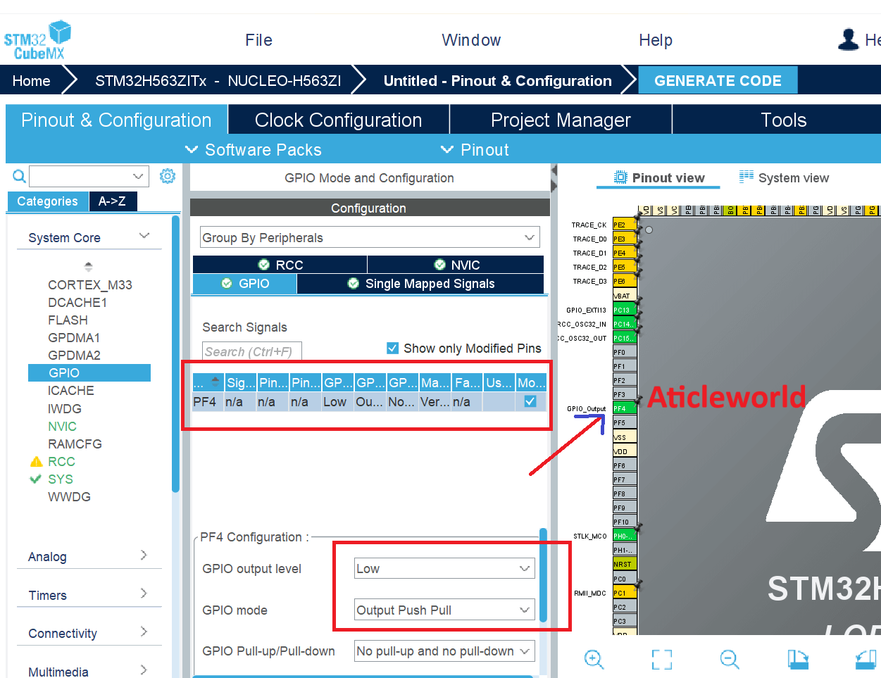
In the GPIO tab, select the Pin Name column and choose PF4 to display the relevant GPIO parameters and configurations for driving the STM32 NUCLEO-H563ZI.
Here’s a breakdown of the key settings:
- GPIO Output Level: By default, it’s set to Low, but you can change it to High to turn on the LED.
- GPIO Mode: The pin is automatically configured to the appropriate alternate function and set to Output Push-Pull mode, which is ideal for driving an LED.
- GPIO Pull-up/Pull-down: Set to No pull-up and No pull-down by default. You can adjust this setting if needed, depending on your application.
- GPIO Maximum Output Speed: Initially set to Low to optimize power consumption. You can increase the speed if higher frequency operation is required for your application.
- User Label: This is a custom name you can assign to the GPIO pin. You can easily locate the GPIO pin by its label using the Find menu.
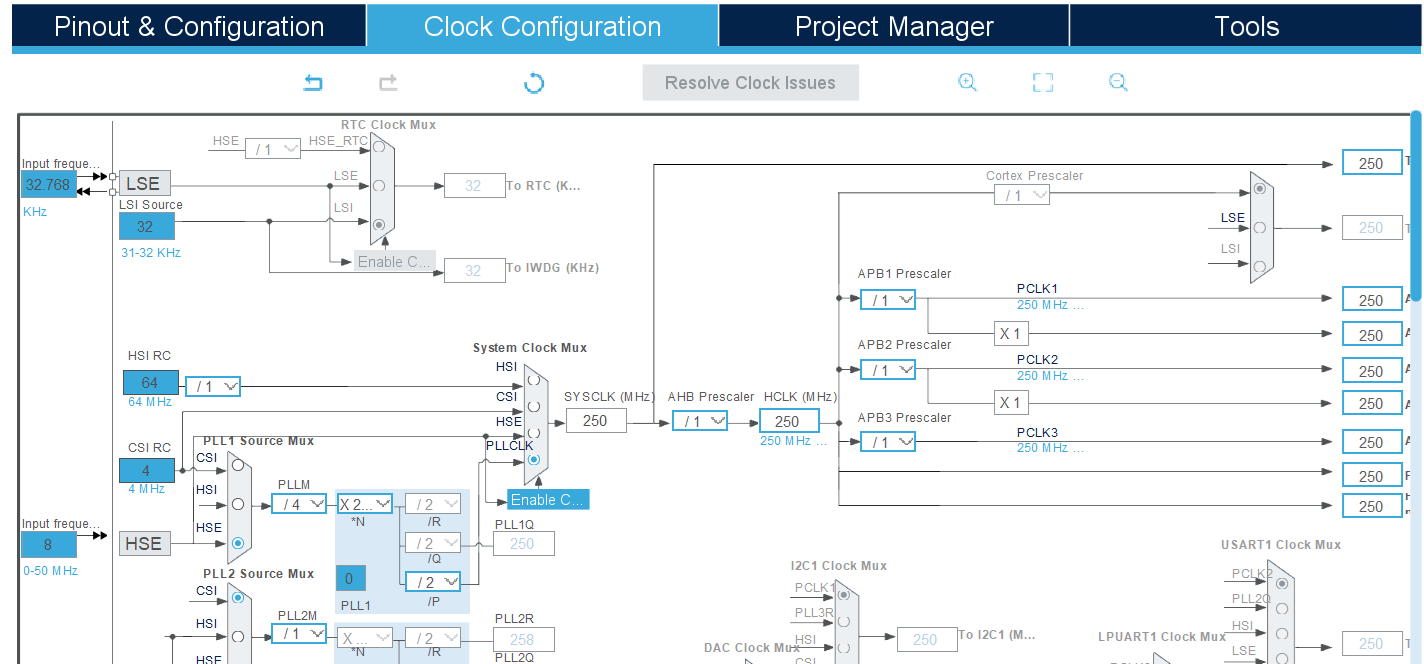
Step: -3 Clock Configuration:
The Clock Configuration tab in STM32CubeMX provides a visual and interactive way to set up the clock system of your STM32 microcontroller. It enables you to configure various clock sources and their derived frequencies for the core, peripherals, and buses.
Key Features:
- Clock Source Selection: Choose between internal (HSI, LSI) and external (HSE, LSE) oscillators, or a PLL for higher frequencies.
- PLL Configuration: Fine-tune the PLL (Phase-Locked Loop) to achieve the desired system clock frequency.
- Bus Frequencies: Configure the AHB (HCLK) and APB (PCLK1/PCLK2) clock prescalers for optimal performance.
- Real-Time Visualization: Instantly see the impact of your settings on system clocks with real-time frequency updates.
- Error Detection: Automatic validation ensures the configuration adheres to the microcontroller’s clock limits.
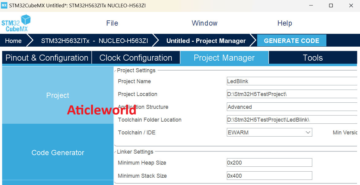
Step: -4 Configure the project and generate source code:
After setting up your clock configuration, proceed to the Project Manager tab to finalize your project settings and generate the source code. In the Project tab:
- Fill the Project Name and Project Location fields.
- Set Toolchain/IDE to STM32CubeIDE.
Before generating the source code, navigate to the Code Generator tab and ensure the following options are enabled for a seamless development experience:
- STM32Cube Firmware Library Package:
- Select Copy all used libraries into the project folder to include all necessary libraries directly in your project, ensuring portability and ease of use.
- Generated Files:
- Enable Keep user code when regenerating to preserve any custom code written in user-defined sections within the STM32CubeMX-generated files during subsequent code generation.
Step: -5 Edit the generated source code:
Once the project files are generated, it’s time to customize the source code to implement your application logic. For this example, we will create a simple LED blink functionality. So let’s modify the code to achieve this.
The following code has been modified to blink the LED connected to PF4 on my board.
C Source Code to Blinking an LED on STM32:
#ifdef __cplusplus
extern "C"
{
#endif

#include "stm32h5xx_hal.h"

#ifdef __cplusplus
}
#endif

/**
 * @file main.c
 * @brief This Source Code to Blinking an LED on STM32is modified
 by AticleWorld for demonstration purposes.
 *
 * @details The provided code is shared "as-is" without any warranties or guarantees
 * of performance, suitability, or correctness. Use it at your own discretion and risk.
 */

/**
 * @brief Enumeration to indicate status.
 */
typedef enum
{
   eSuccess = 0, /**< Indicates successful operation */
   eError = 1    /**< Indicates error in operation */
} eStatus;

/**
 * @brief Configures the system clock.
 *
 * This function initializes the RCC (Reset and Clock Control) to configure
 * the system clock using the HSE (High-Speed External) oscillator with the PLL.
 *
 * @retval eSuccess if the configuration is successful.
 * @retval eError if an error occurs during configuration.
 */
eStatus SystemClock_Config(void)
{
   eStatus ret = eSuccess; // Default status

   RCC_OscInitTypeDef RCC_OscInitStruct = {0};
   RCC_ClkInitTypeDef RCC_ClkInitStruct = {0};

   /** Configure the main internal regulator output voltage */
   __HAL_PWR_VOLTAGESCALING_CONFIG(PWR_REGULATOR_VOLTAGE_SCALE0);

   while (!__HAL_PWR_GET_FLAG(PWR_FLAG_VOSRDY))
   {
   }

   /** Initialize the RCC Oscillators */
   RCC_OscInitStruct.OscillatorType = RCC_OSCILLATORTYPE_HSE;
   RCC_OscInitStruct.HSEState = RCC_HSE_BYPASS;
   RCC_OscInitStruct.PLL.PLLState = RCC_PLL_ON;
   RCC_OscInitStruct.PLL.PLLSource = RCC_PLL1_SOURCE_HSE;
   RCC_OscInitStruct.PLL.PLLM = 4;
   RCC_OscInitStruct.PLL.PLLN = 250;
   RCC_OscInitStruct.PLL.PLLP = 2;
   RCC_OscInitStruct.PLL.PLLQ = 2;
   RCC_OscInitStruct.PLL.PLLR = 2;
   RCC_OscInitStruct.PLL.PLLRGE = RCC_PLL1_VCIRANGE_1;
   RCC_OscInitStruct.PLL.PLLVCOSEL = RCC_PLL1_VCORANGE_WIDE;
   RCC_OscInitStruct.PLL.PLLFRACN = 0;

   if (HAL_RCC_OscConfig(&RCC_OscInitStruct) != HAL_OK)
   {
      ret = eError;
   }

   if (ret != eError)
   {
      /** Initialize the CPU, AHB, and APB buses clocks */
      RCC_ClkInitStruct.ClockType =
            RCC_CLOCKTYPE_HCLK | RCC_CLOCKTYPE_SYSCLK |
      RCC_CLOCKTYPE_PCLK1 | RCC_CLOCKTYPE_PCLK2 | RCC_CLOCKTYPE_PCLK3;

      RCC_ClkInitStruct.SYSCLKSource = RCC_SYSCLKSOURCE_PLLCLK;
      RCC_ClkInitStruct.AHBCLKDivider = RCC_SYSCLK_DIV1;
      RCC_ClkInitStruct.APB1CLKDivider = RCC_HCLK_DIV1;
      RCC_ClkInitStruct.APB2CLKDivider = RCC_HCLK_DIV1;
      RCC_ClkInitStruct.APB3CLKDivider = RCC_HCLK_DIV1;

      if (HAL_RCC_ClockConfig(&RCC_ClkInitStruct, FLASH_LATENCY_5) != HAL_OK)
      {
         ret = eError;
      }

      if (ret != eError)
      {
         /** Configure the programming delay */
         __HAL_FLASH_SET_PROGRAM_DELAY(FLASH_PROGRAMMING_DELAY_2);
      }
   }

   return ret;
}

/**
 * @brief Initializes the GPIO pins.
 *
 * This function configures GPIOF pin 4 as a push-pull output
 * for controlling an LED.
 *
 * @retval None
 */
static void MX_GPIO_Init(void)
{
   GPIO_InitTypeDef GPIO_InitStruct = {0};

   /* Enable the GPIOF clock */
   __HAL_RCC_GPIOF_CLK_ENABLE();

   /* Configure GPIO pin output level */
   HAL_GPIO_WritePin(GPIOF, GPIO_PIN_4, GPIO_PIN_RESET);

   /* Configure GPIO pin PF4 */
   GPIO_InitStruct.Pin = GPIO_PIN_4;
   GPIO_InitStruct.Mode = GPIO_MODE_OUTPUT_PP;
   GPIO_InitStruct.Pull = GPIO_NOPULL;
   GPIO_InitStruct.Speed = GPIO_SPEED_FREQ_VERY_HIGH;
   HAL_GPIO_Init(GPIOF, &GPIO_InitStruct);
}

/**
 * @brief Main function.
 *
 * The entry point of the program initializes the HAL library, configures the
 * system clock, initializes GPIO, and enters an infinite loop.
 *
 * @retval int This function does not return.
 */
int main(void)
{
   eStatus ret = eSuccess;
   /* Initialize the HAL Library */
   HAL_StatusTypeDef ok = HAL_Init();
   if (ok == HAL_OK)
   {
      /* Configure the system clock */
      ret = SystemClock_Config();
      if (ret != eError)
      {

         /* Initialize all configured peripherals */
         MX_GPIO_Init();

         while (1)
         {
            // LED ON
            HAL_GPIO_WritePin(GPIOF, GPIO_PIN_4, GPIO_PIN_SET);
            HAL_Delay(500); // Delay for 500ms

            // LED OFF
            HAL_GPIO_WritePin(GPIOF, GPIO_PIN_4, GPIO_PIN_RESET);
            HAL_Delay(500); // Delay for 500ms
         }
      }
   }
   else
   {
      ret = eError;
   }

   return (ret == eSuccess);
}
C++ Source Code to Blinking an LED on STM32:
#include "stdio.h"
extern "C"
{
#include "stm32h5xx_hal.h"
}

/**
 * @brief Enumeration to indicate status.
 */
enum class Status
{
   Success = 0, /**< Indicates successful operation */
   Error = 1    /**< Indicates error in operation */
};

/**
 * @brief Class to configure the system clock.
 */
class SystemClock
{
public:
   /**
    * @brief Configures the system clock.
    *
    * Initializes the RCC (Reset and Clock Control) to configure
    * the system clock using the HSE (High-Speed External) oscillator with the PLL.
    *
    * @return Status::Success if the configuration is successful.
    * @return Status::Error if an error occurs during configuration.
    */
   static Status Configure()
   {
      Status ret = Status::Success;
      RCC_OscInitTypeDef RCC_OscInitStruct = {0};
      RCC_ClkInitTypeDef RCC_ClkInitStruct = {0};

      // Configure the main internal regulator output voltage
      __HAL_PWR_VOLTAGESCALING_CONFIG(PWR_REGULATOR_VOLTAGE_SCALE0);
      while (!__HAL_PWR_GET_FLAG(PWR_FLAG_VOSRDY))
      {
      }

      // Initialize the RCC Oscillators
      RCC_OscInitStruct.OscillatorType = RCC_OSCILLATORTYPE_HSE;
      RCC_OscInitStruct.HSEState = RCC_HSE_BYPASS;
      RCC_OscInitStruct.PLL.PLLState = RCC_PLL_ON;
      RCC_OscInitStruct.PLL.PLLSource = RCC_PLL1_SOURCE_HSE;
      RCC_OscInitStruct.PLL.PLLM = 4;
      RCC_OscInitStruct.PLL.PLLN = 250;
      RCC_OscInitStruct.PLL.PLLP = 2;
      RCC_OscInitStruct.PLL.PLLQ = 2;
      RCC_OscInitStruct.PLL.PLLR = 2;
      RCC_OscInitStruct.PLL.PLLRGE = RCC_PLL1_VCIRANGE_1;
      RCC_OscInitStruct.PLL.PLLVCOSEL = RCC_PLL1_VCORANGE_WIDE;
      RCC_OscInitStruct.PLL.PLLFRACN = 0;

      if (HAL_RCC_OscConfig(&RCC_OscInitStruct) != HAL_OK)
      {
         ret = Status::Error;
      }

      if (ret != Status::Error)
      {
         // Initialize the CPU, AHB, and APB buses clocks
         RCC_ClkInitStruct.ClockType = RCC_CLOCKTYPE_HCLK | RCC_CLOCKTYPE_SYSCLK | RCC_CLOCKTYPE_PCLK1
                                       | RCC_CLOCKTYPE_PCLK2 | RCC_CLOCKTYPE_PCLK3;
         RCC_ClkInitStruct.SYSCLKSource = RCC_SYSCLKSOURCE_PLLCLK;
         RCC_ClkInitStruct.AHBCLKDivider = RCC_SYSCLK_DIV1;
         RCC_ClkInitStruct.APB1CLKDivider = RCC_HCLK_DIV1;
         RCC_ClkInitStruct.APB2CLKDivider = RCC_HCLK_DIV1;
         RCC_ClkInitStruct.APB3CLKDivider = RCC_HCLK_DIV1;

         if (HAL_RCC_ClockConfig(&RCC_ClkInitStruct, FLASH_LATENCY_5) != HAL_OK)
         {
            ret = Status::Error;
         }

         if (ret != Status::Error)
         {
            // Configure the programming delay
            __HAL_FLASH_SET_PROGRAM_DELAY(FLASH_PROGRAMMING_DELAY_2);
         }
      }

      return ret;
   }
};

/**
 * @brief Class to handle GPIO initialization.
 */
class GPIO
{
public:
   /**
    * @brief Initializes the GPIO pins.
    *
    * Configures GPIOF pin 4 as a push-pull output for controlling an LED.
    */
   static void Init()
   {
      GPIO_InitTypeDef GPIO_InitStruct = {0};

      // Enable the GPIOF clock
      __HAL_RCC_GPIOF_CLK_ENABLE();

      // Configure GPIO pin output level
      HAL_GPIO_WritePin(GPIOF, GPIO_PIN_4, GPIO_PIN_RESET);

      // Configure GPIO pin PF4
      GPIO_InitStruct.Pin = GPIO_PIN_4;
      GPIO_InitStruct.Mode = GPIO_MODE_OUTPUT_PP;
      GPIO_InitStruct.Pull = GPIO_NOPULL;
      GPIO_InitStruct.Speed = GPIO_SPEED_FREQ_VERY_HIGH;
      HAL_GPIO_Init(GPIOF, &GPIO_InitStruct);
   }
};

/**
 * @brief Main LED controller application.
 */
class LedController
{
public:
   /**
    * @brief Starts the LED blink sequence.
    *
    * Toggles the LED connected to GPIOF pin 4 in an infinite loop.
    */
   void Run()
   {
      while (true)
      {
         // LED ON
         HAL_GPIO_WritePin(GPIOF, GPIO_PIN_4, GPIO_PIN_SET);
         HAL_Delay(500); // Delay for 500ms

         // LED OFF
         HAL_GPIO_WritePin(GPIOF, GPIO_PIN_4, GPIO_PIN_RESET);
         HAL_Delay(500); // Delay for 500ms
      }
   }
};

/**
 * @brief Main entry point of the program.
 *
 * Initializes the HAL library, configures the system clock, initializes GPIO,
 * and starts the LED blink sequence.
 *
 * @return int 0 on successful execution, 1 on error.
 */
int main()
{
   HAL_StatusTypeDef halStatus = HAL_Init();
   if (halStatus != HAL_OK)
   {
      return static_cast<int>(Status::Error);
   }

   if (SystemClock::Configure() == Status::Error)
   {
      return static_cast<int>(Status::Error);
   }

   GPIO::Init();

   LedController ledController;
   ledController.Run();

   return static_cast<int>(Status::Success);
}
In the code above, I have used the HAL_GPIO_WritePin() function to set the state of the GPIO pin. However, if you prefer, you can use the HAL_GPIO_TogglePin() function, which toggles the current state of the GPIO pin.
Also, we have used the HAL_Delay() built-in function to introduce a delay between each pin state change. This function is particularly convenient for such projects, especially if it’s your first time working with STM32. If you prefer, there are other alternative methods also to introduce delays. I will cover these options in a separate blog post, where I will explore all the different ways you can implement delays in your project.
I hope this piece of code to blinking an LED on STM32 helps you in your STM32 projects! If you have any questions or need further clarification, feel free to leave a comment below—I’d be happy to assist you. Don’t hesitate to share any challenges you’ve faced or insights you’ve gained while working with GPIO pins.
If you found this guide useful, please consider sharing it with your friends and colleagues on your social media platforms. Your support helps others discover this resource and strengthens the STM32 community. Thanks for sharing!
Happy Coding. 🤩