In this article, we will guide you through the steps to create a simple project that enables and handles external interrupts to the STM32 microcontroller. For this tutorial, we’ll use the STM32 NUCLEO-H563ZI development board.
In this tutorial, we will generate the necessary code using STM32CubeMX and utilize HAL functions for an efficient implementation.
So let’s get started.
In STM32 MCUs Most of the GPIO pins on can trigger an interrupt.
The EXTI (EXTernal Interrupt/Event) controller consists of up to 40 edge detectors for generating event/interrupt requests on STM32L47x/L48x devices. Each input line can be independently configured to select the type (interrupt or event) and the corresponding trigger event (rising, falling, or both).
Most of the GPIO pins on STM32 MCUs can trigger an interrupt. This page explains how to configure that in STM32CubeIDE and how to deal with it in C.
Prerequisites: –
- STM32CubeMX
- NUCLEO-H563ZI development board.
- USB cables Type-C
How to Configure EXTI in STM32 to Turn on an LED with a Button Press
In this blog post, we will walk you through configuring an External Interrupt (EXTI) in STM32 to turn on an LED when a user button is pressed. By the end of this guide, you will understand how to use EXTI and NVIC to achieve this functionality step-by-step.
Objectives of this project:
- Set Up GPIO for EXTI: Configure the GPIO pin connected to the user button as an external interrupt with a falling edge trigger using STM32CubeIDE.
- Configure the NVIC (Nested Vectored Interrupt Controller): Learn how to set up the NVIC to handle external interrupts effectively.
- Test the Setup: Verify the functionality by pressing the user button, ensuring that the LED turns on when triggered.
Steps to generate External Interrupt Code for STM32:
In the below section, I will guide you step-by-step on how to generate code for external interrupt for stm32. By following these steps, you will learn how to use STM32CubeMX to configure the microcontroller’s pins, and how to write the corresponding code with STM32 HAL libraries.
Step: -1 Create Project Using STM32CubeMX:
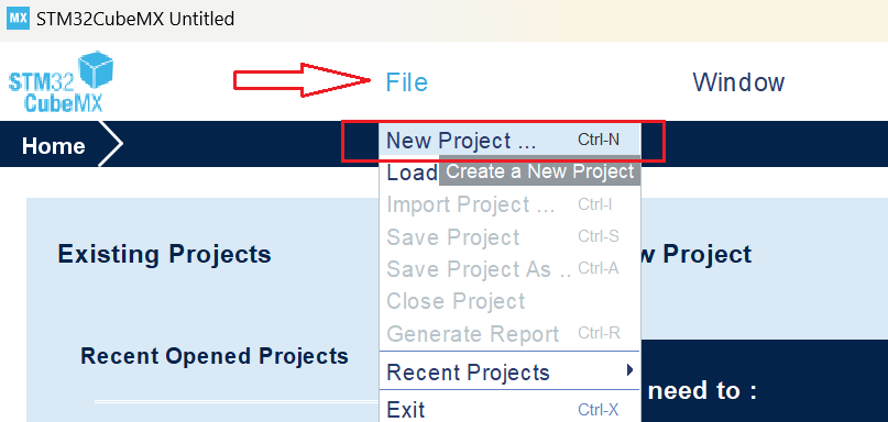
Launch STM32CubeMX: Open the STM32CubeMX application on your system.
Create a New Project: Open STM32CubeMX and navigate to File > New Project > Create New Project.
Select Your Board OR MCU: Go to the Board Selector tab and enter the name of your STM32 development board. For this tutorial, we are using the NUCLEO-H563ZI board.
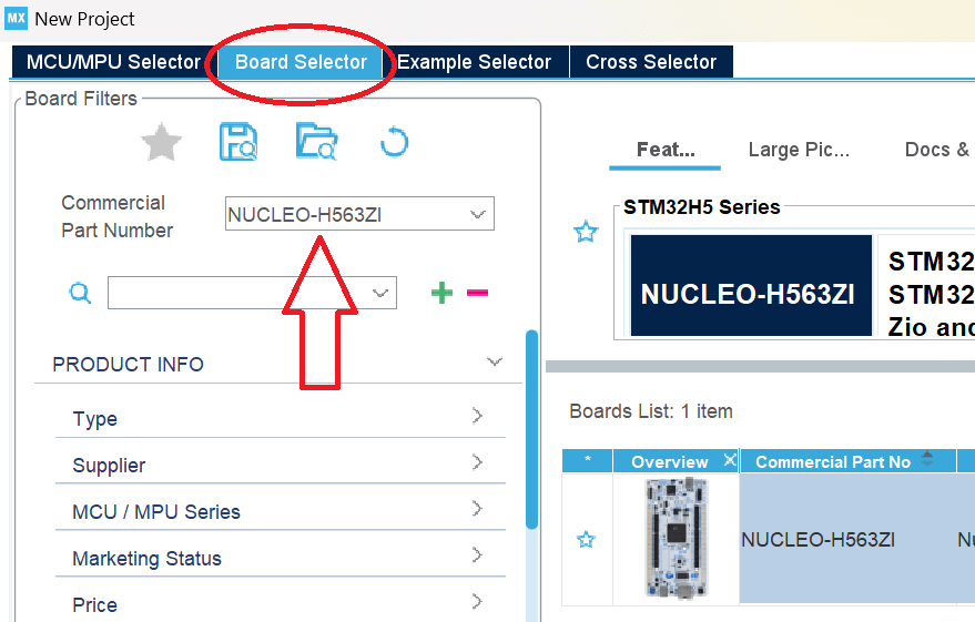
Click on Start Project and select without trustZone activated or with trustZone activated. I will select without trustZone activated here.

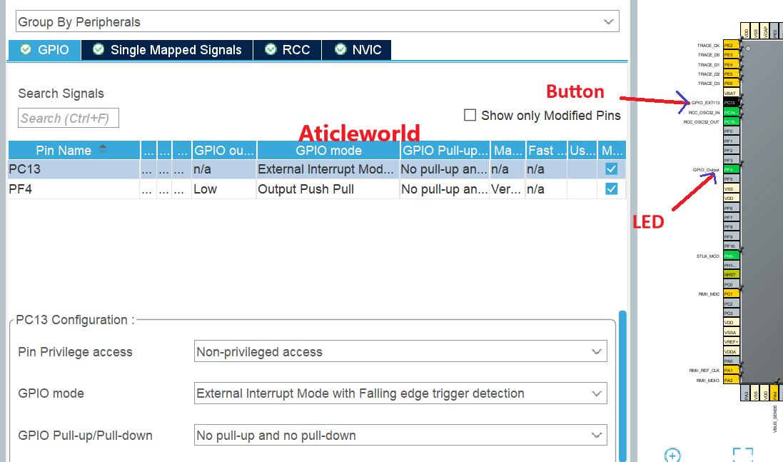
Step: -2 Pinout Configuration:
Navigate to the ‘Pinout & Configuration tab’ in STM32CubeMX. Identify the GPIO pin connected to the LED based on your board’s documentation. For instance, on the STM32H6ZI board, the user yellow LED (LD2) is connected to PF4 and the user button PC13.
In this example, we will configure PF4 as the LED pin and PC13 as the Button pin (configure a button pin as GPIO_EXTI).
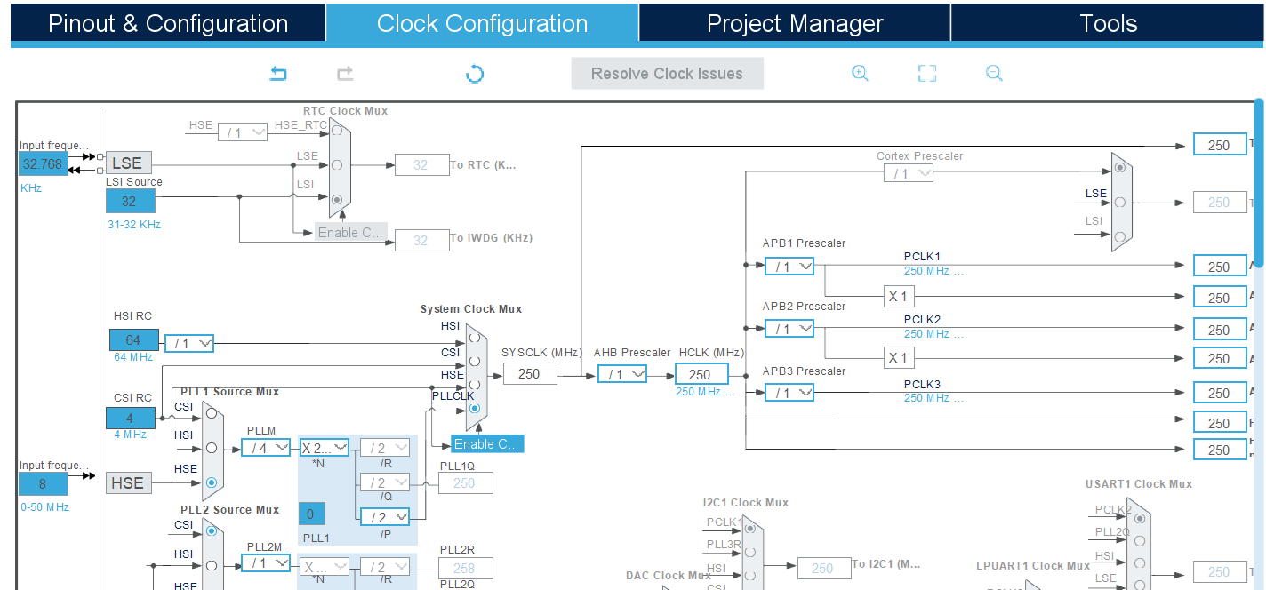
Step: -3 Clock Configuration:
The Clock Configuration tab in STM32CubeMX provides a visual and interactive way to set up the clock system of your STM32 microcontroller. It enables you to configure various clock sources and their derived frequencies for the core, peripherals, and buses.
Key Features:
- Clock Source Selection: Choose between internal (HSI, LSI) and external (HSE, LSE) oscillators, or a PLL for higher frequencies.
- PLL Configuration: Fine-tune the PLL (Phase-Locked Loop) to achieve the desired system clock frequency.
- Bus Frequencies: Configure the AHB (HCLK) and APB (PCLK1/PCLK2) clock prescalers for optimal performance.
- Real-Time Visualization: Instantly see the impact of your settings on system clocks with real-time frequency updates.
- Error Detection: Automatic validation ensures the configuration adheres to the microcontroller’s clock limits.
Step: -4 Configure the project and generate source code:
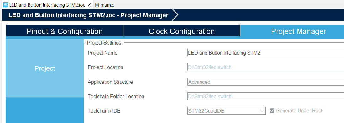
After setting up your clock configuration, proceed to the Project Manager tab to finalize your project settings and generate the source code. In the Project tab:
- Fill the Project Name and Project Location fields.
- Set Toolchain/IDE to STM32CubeIDE.
Before generating the source code, navigate to the Code Generator tab and ensure the following options are enabled for a seamless development experience:
- STM32Cube Firmware Library Package:
- Select Copy all used libraries into the project folder to include all necessary libraries directly in your project, ensuring portability and ease of use.
- Generated Files:
- Enable Keep user code when regenerating to preserve any custom code written in user-defined sections within the STM32CubeMX-generated files during subsequent code generation.
Step: -5 Edit the generated source code:
Now you need to customize the generated source code as per your requirements. For this example, we will create a simple program to control LED using a button with the help of an external interrupt. So, let’s modify the code to achieve this.
The following code has been modified to blink the LED connected to PF4 on my board by pressing a button that connected to PC13 (configure a button pin as GPIO_EXTI).
#ifdef __cplusplus
extern "C"
{
#endif
#include "stm32h5xx_hal.h"
#ifdef __cplusplus
}
#endif

/**
 * @brief Debounce delay in milliseconds.
 */
#define DEBOUNCE_DELAY 200

/**
 * @brief Define the button pin (PC13) and LED pin (PF4).
 */
#define BUTTON_PIN GPIO_PIN_13
#define LED_PIN GPIO_PIN_4

/**
 * @file main.c
 * @brief This code is modified by AticleWorld for demonstration purposes.
 */

/**
 * @brief Enumeration to indicate status.
 */
typedef enum
{
   eSuccess = 0, /**< Indicates successful operation */
   eError = 1    /**< Indicates error in operation */
} eStatus;

/**
 * @brief Enumeration to indicate LED states.
 */
typedef enum
{
   eLedOff = 0, /**< Indicates LED off */
   eLedOn = 1   /**< Indicates LED on */
} eLedOnOffStatus;

/**
 * @brief Enumeration to indicate button press state.
 */
typedef enum
{
   eButtonNotPressed = 0, /**< Button is not pressed */
   eButtonPressed = 1     /**< Button is pressed */
} eButtonPressState;

/**
 * @brief Global variables to track states.
 */
static volatile eLedOnOffStatus ledState = eLedOn;  // Track LED state
static volatile eButtonPressState buttonState = eButtonNotPressed; // Track button state

/**
 * @brief This function handles EXTI Line13 interrupt.
 */
extern "C"
{
   void EXTI13_IRQHandler(void)
   {
      HAL_GPIO_EXTI_IRQHandler(GPIO_PIN_13);
   }

   void HAL_GPIO_EXTI_Falling_Callback(uint16_t GPIO_Pin)
   {
      /* Prevent unused argument(s) compilation warning */
      UNUSED(GPIO_Pin);

      buttonState = eButtonPressed; // Update button state

      // Toggle the LED state
      switch (ledState)
      {
         case eLedOff:
            ledState = eLedOn;
            break;
         case eLedOn:
            ledState = eLedOff;
            break;
         default:
            break;
      }
   }
}

/**
 * @brief Configures the system clock.
 */
eStatus SystemClock_Config(void)
{
   eStatus ret = eSuccess;
   RCC_OscInitTypeDef RCC_OscInitStruct = {0};
   RCC_ClkInitTypeDef RCC_ClkInitStruct = {0};

   __HAL_PWR_VOLTAGESCALING_CONFIG(PWR_REGULATOR_VOLTAGE_SCALE0);
   while (!__HAL_PWR_GET_FLAG(PWR_FLAG_VOSRDY))
   {
   }

   RCC_OscInitStruct.OscillatorType = RCC_OSCILLATORTYPE_HSE;
   RCC_OscInitStruct.HSEState = RCC_HSE_BYPASS;
   RCC_OscInitStruct.PLL.PLLState = RCC_PLL_ON;
   RCC_OscInitStruct.PLL.PLLSource = RCC_PLL1_SOURCE_HSE;
   RCC_OscInitStruct.PLL.PLLM = 4;
   RCC_OscInitStruct.PLL.PLLN = 250;
   RCC_OscInitStruct.PLL.PLLP = 2;
   RCC_OscInitStruct.PLL.PLLQ = 2;
   RCC_OscInitStruct.PLL.PLLR = 2;
   RCC_OscInitStruct.PLL.PLLRGE = RCC_PLL1_VCIRANGE_1;
   RCC_OscInitStruct.PLL.PLLVCOSEL = RCC_PLL1_VCORANGE_WIDE;
   RCC_OscInitStruct.PLL.PLLFRACN = 0;

   if (HAL_RCC_OscConfig(&RCC_OscInitStruct) != HAL_OK)
   {
      ret = eError;
   }

   if (ret != eError)
   {
      RCC_ClkInitStruct.ClockType =
            RCC_CLOCKTYPE_HCLK | RCC_CLOCKTYPE_SYSCLK |
      RCC_CLOCKTYPE_PCLK1 | RCC_CLOCKTYPE_PCLK2 | RCC_CLOCKTYPE_PCLK3;
      RCC_ClkInitStruct.SYSCLKSource = RCC_SYSCLKSOURCE_PLLCLK;
      RCC_ClkInitStruct.AHBCLKDivider = RCC_SYSCLK_DIV1;
      RCC_ClkInitStruct.APB1CLKDivider = RCC_HCLK_DIV1;
      RCC_ClkInitStruct.APB2CLKDivider = RCC_HCLK_DIV1;
      RCC_ClkInitStruct.APB3CLKDivider = RCC_HCLK_DIV1;

      if (HAL_RCC_ClockConfig(&RCC_ClkInitStruct, FLASH_LATENCY_5) != HAL_OK)
      {
         ret = eError;
      }

      if (ret != eError)
      {
         __HAL_FLASH_SET_PROGRAM_DELAY(FLASH_PROGRAMMING_DELAY_2);
      }
   }

   return ret;
}

/**
 * @brief Initializes the GPIO pins.
 */
static void MX_GPIO_Init(void)
{
   GPIO_InitTypeDef GPIO_InitStruct = {0};

   __HAL_RCC_GPIOF_CLK_ENABLE();
   __HAL_RCC_GPIOC_CLK_ENABLE();

   HAL_GPIO_WritePin(GPIOF, GPIO_PIN_4, GPIO_PIN_RESET);

   GPIO_InitStruct.Pin = GPIO_PIN_4;
   GPIO_InitStruct.Mode = GPIO_MODE_OUTPUT_PP;
   GPIO_InitStruct.Pull = GPIO_NOPULL;
   GPIO_InitStruct.Speed = GPIO_SPEED_FREQ_VERY_HIGH;
   HAL_GPIO_Init(GPIOF, &GPIO_InitStruct);

   GPIO_InitStruct.Pin = GPIO_PIN_13;
   GPIO_InitStruct.Mode = GPIO_MODE_IT_FALLING;
   GPIO_InitStruct.Pull = GPIO_NOPULL;
   HAL_GPIO_Init(GPIOC, &GPIO_InitStruct);

   HAL_NVIC_SetPriority(EXTI13_IRQn, 0, 0);
   HAL_NVIC_EnableIRQ(EXTI13_IRQn);
}

/**
 * @brief Main function.
 */
int main(void)
{
   eStatus ret = eSuccess;

   HAL_StatusTypeDef ok = HAL_Init();
   if (ok == HAL_OK)
   {
      ret = SystemClock_Config();
      if (ret != eError)
      {
         MX_GPIO_Init();

         while (1)
         {
            // Check if the button is pressed
            if (buttonState == eButtonPressed)
            {
               buttonState = eButtonNotPressed; // Reset button state

               if (ledState == eLedOff)
               {
                  HAL_GPIO_WritePin(GPIOF, LED_PIN, GPIO_PIN_SET); // Turn ON LED
               }
               else
               {
                  HAL_GPIO_WritePin(GPIOF, LED_PIN, GPIO_PIN_RESET); // Turn OFF LED
               }
            }
         }
      }
   }
   else
   {
      ret = eError;
   }

   return (ret == eSuccess);
}
How code works:
This code shows how you can control a LED using a push-button using STM32 HAL (Hardware Abstraction Layer).
- When the button is pressed, a falling-edge interrupt on pin 13 triggers HAL_GPIO_EXTI_Falling_Callback, which updates buttonState to eButtonPressed and toggles ledState.
- The main loop checks buttonState and, if pressed, resets it to eButtonNotPressed and toggles the LED based on ledState.
- Debounce ensures reliable detection by preventing false triggers due to mechanical bouncing.
STM32 GPIO C++ Source code to control Led with the help of button that configured as EXTI:
#include "stm32h5xx_hal.h"
#include <memory>

/**
 * @brief Interface for LED control
 */
class ILedControl
{
public:
   virtual void TurnOn() = 0;
   virtual void TurnOff() = 0;
   virtual bool IsOn() const = 0;
   virtual ~ILedControl() = default;
};

/**
 * @brief Implementation of LED control
 */
class LedControl : public ILedControl
{
private:
   GPIO_TypeDef* m_gpioPort;
   uint16_t m_gpioPin;
   bool m_isOn;

public:
   LedControl(GPIO_TypeDef* gpioPort, uint16_t gpioPin) : m_gpioPort(gpioPort), m_gpioPin(gpioPin), m_isOn(false)
   {
      Init();
   }

   void Init()
   {
      __HAL_RCC_GPIOF_CLK_ENABLE();
      GPIO_InitTypeDef GPIO_InitStruct = {0};
      GPIO_InitStruct.Pin = m_gpioPin;
      GPIO_InitStruct.Mode = GPIO_MODE_OUTPUT_PP;
      GPIO_InitStruct.Pull = GPIO_NOPULL;
      GPIO_InitStruct.Speed = GPIO_SPEED_FREQ_VERY_HIGH;
      HAL_GPIO_Init(m_gpioPort, &GPIO_InitStruct);
      HAL_GPIO_WritePin(m_gpioPort, m_gpioPin, GPIO_PIN_RESET);
   }

   void TurnOn() override
   {
      HAL_GPIO_WritePin(m_gpioPort, m_gpioPin, GPIO_PIN_SET);
      m_isOn = true;
   }

   void TurnOff() override
   {
      HAL_GPIO_WritePin(m_gpioPort, m_gpioPin, GPIO_PIN_RESET);
      m_isOn = false;
   }

   bool IsOn() const override
   {
      return m_isOn;
   }
};

/**
 * @brief Interface for Button handling
 */
class IButtonHandler
{
public:
   virtual void Init() = 0;
   virtual void HandlePress() = 0;
   virtual ~IButtonHandler() = default;
};

/**
 * @brief Implementation of Button handling
 */
class ButtonHandler : public IButtonHandler
{
private:
   GPIO_TypeDef* m_gpioPort;
   uint16_t m_gpioPin;
   ILedControl& m_ledControl;

public:
   ButtonHandler(GPIO_TypeDef* gpioPort, uint16_t gpioPin, ILedControl& ledControl)
         : m_gpioPort(gpioPort), m_gpioPin(gpioPin), m_ledControl(ledControl)
   {
   }

   void Init() override
   {
      __HAL_RCC_GPIOC_CLK_ENABLE();
      GPIO_InitTypeDef GPIO_InitStruct = {0};
      GPIO_InitStruct.Pin = m_gpioPin;
      GPIO_InitStruct.Mode = GPIO_MODE_IT_FALLING;
      GPIO_InitStruct.Pull = GPIO_NOPULL;
      HAL_GPIO_Init(m_gpioPort, &GPIO_InitStruct);

      HAL_NVIC_SetPriority(EXTI13_IRQn, 0, 0);
      HAL_NVIC_EnableIRQ(EXTI13_IRQn);
   }

   void HandlePress() override
   {
      if (m_ledControl.IsOn())
      {
         m_ledControl.TurnOff();
      }
      else
      {
         m_ledControl.TurnOn();
      }
   }
};

/**
 * @brief Singleton for handling the main application
 */
class Application
{
private:
   static Application* instance;
   std::unique_ptr<ILedControl> ledControl;
   std::unique_ptr<IButtonHandler> buttonHandler;

   Application()
         : ledControl(std::make_unique<LedControl>(GPIOF, GPIO_PIN_4)),
           buttonHandler(std::make_unique<ButtonHandler>(GPIOC, GPIO_PIN_13, *ledControl))
   {
   }

public:
   static Application* GetInstance()
   {
      if (instance == nullptr)
      {
         instance = new Application();
      }
      return instance;
   }

   void Init()
   {
      HAL_Init();
      buttonHandler->Init();
   }

   void Run()
   {
      while (true)
      {
         // Application main loop
      }
   }

   void OnButtonPress()
   {
      buttonHandler->HandlePress();
   }
};

Application* Application::instance = nullptr;

/**
 * @brief EXTI interrupt handler
 */
extern "C"
{
   void EXTI13_IRQHandler(void)
   {
      HAL_GPIO_EXTI_IRQHandler(GPIO_PIN_13);
   }

   void HAL_GPIO_EXTI_Falling_Callback(uint16_t GPIO_Pin)
   {
      if (GPIO_Pin == GPIO_PIN_13)
      {
         Application::GetInstance()->OnButtonPress();
      }
   }
}

/**
 * @brief Main function
 */
int main(void)
{
   auto app = Application::GetInstance();
   app->Init();
   app->Run();
   return 0;
}
I hope this piece of code helps you in your STM32 projects! If you have any questions or need further clarification, feel free to leave a comment below—I’d be happy to assist you. Don’t hesitate to share any challenges you’ve faced or insights you’ve gained while working with GPIO pins.
If you found this guide useful, please consider sharing it with your friends and colleagues on your social media platforms. Your support helps others discover this resource and strengthens the STM32 community. Thanks for sharing!
Happy Coding. 🤩