The 7805-voltage regulator has been the silent hero behind countless reliable electronic designs for decades. Despite today’s advanced switching regulators and low-dropout designs, the 7805 remains a benchmark of simplicity, stability, and durability.
In this blog post, we will explore how the 7805-voltage regulator works, the real-world issues engineers often encounter, and some field-proven solutions that help circuits stay stable and efficient over years of operation.
What Is a 7805 Voltage Regulator?
The 7805 is a linear fixed voltage regulator that outputs a constant +5V DC from a higher input voltage (typically between 7V and 35V).
It’s part of the 78xx regulator family, where “xx” represents the output voltage — for example:
| Regulator | Output Voltage |
|---|---|
| 7805 | +5V |
| 7809 | +9V |
| 7812 | +12V |
The 7805 is one of the most popular in this family because many circuits and microcontrollers work on 5V. It comes in a few different package styles — the TO-220 (bigger, for higher current) and the TO-92 (smaller, for low-power use). That makes it suitable for breadboards, school projects, embedded systems, and even professional designs.
What makes the 7805 so dependable is its built-in protection — it can handle overheating and short circuits without getting damaged. Plus, it gives a clean and stable 5V output, which keeps your circuit safe from voltage noise or sudden spikes.
One big reason engineers love the 7805 is because it delivers a clean and steady 5V output. It protects your circuit from voltage spikes and electrical noise, keeping things safe and stable. That means your microcontrollers, sensors, and ICs always get a smooth, reliable power supply — which is exactly what every good design needs.
Features of the 7805:
Now, let’s look at some of the important features of the 7805-voltage regulator.
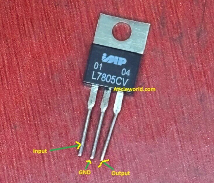
The 7805 belongs to the L78 series of voltage regulators and is commonly available as L7805CV, which is manufactured by STMicroelectronics. It is one of the most widely used versions of the 7805 and comes with several built-in protection and reliability features that make it a favorite among engineers.
Keep in mind that different manufacturers may have slight variations in specifications, so it is always a good idea to check the datasheet of the exact 7805 regulator you’re using for detailed information.
- Output current up to 1.5 A.
- Output voltages of 5; 6; 8; 8.5; 9; 12; 15; 18; 24 V.
- Thermal overload protection.
- Short circuit protection.
- Output transition SOA protection.
- 2 % output voltage tolerance (A version).
- Guaranteed in extended temperature range (A version).
Pin Diagram of 7805 Voltage Regulator IC:
As mentioned earlier, the 7805 is a three-terminal voltage regulator IC. These three pins are:
- Input (Pin 1) – This is where you connect the unregulated DC voltage (usually between 7V and 35V).
- Ground (Pin 2) – This pin is connected to the circuit’s ground reference.
- Output (Pin 3) – This pin provides the regulated +5V output.
The pin description of the 7805 is described in the following table:
| Pin 1 is the INPUT Pin. A positive unregulated voltage is given as input to this pin. | ||
| Pin 2 is the GROUND Pin. It is common to both Input and Output. | ||
| Pin 3 is the OUTPUT Pin. The output regulated 5V is taken at this pin of the IC. |
How the 7805 Voltage Regulator Works:
The 7805 is one of the most popular linear voltage regulators used in electronics. Inside this compact IC lies some elegant analog engineering that ensures your circuits receive a stable and reliable 5-volt supply, even when the input voltage or load fluctuates.
Internally, the 7805 contains three key building blocks:
- A precision voltage reference (bandgap reference)
- An error amplifier
- A series pass transistor
Here is how it works step by step:
The regulator continuously monitors a small fraction of its output voltage and compares it with its internal reference voltage. If the output voltage starts to drift — say due to a change in input voltage or load — the error amplifier quickly reacts by adjusting the drive to the series pass transistor.
This transistor acts like a variable resistor, automatically controlling how much current passes through it to maintain a steady 5V output.
This closed-loop feedback system ensures:
🔹Very low ripple and noise
🔹 Excellent load and line regulation
🔹 Smooth, reliable operation.
Understanding the 7805 Voltage Regulator Basic Circuit:
As discussed earlier, a regulated power supply ensures that the output voltage remains constant, even when the input voltage or load conditions vary. The 7805 voltage regulator IC is one of the most popular and reliable choices for generating a stable 5V DC output from a higher, unregulated DC source.
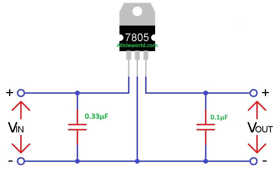
According to the manufacturer’s datasheet, the basic circuit configuration for the 7805 is quite simple. In most cases, only a couple of external capacitors are needed to ensure stable operation and improved transient response.
Component Description:
Above have mentioned the standard circuit of the 7805 IC. Let’s see about the component use in the above circuit.
Input Voltage (VIN):
This is the unregulated DC input applied to the 7805. The input voltage must be at least 7V (and typically less than 20V) to maintain a stable 5V output.
Input Capacitor (0.33µF):
- 0.33 μF (ceramic or film) placed as close as possible to the VIN and GND pins.
- Why: helps filter high-frequency noise and prevents oscillation when the regulator is some distance from the bulk input filter.
Output Capacitor (0.1µF):
- 0.1 μF (ceramic) placed as close as possible to the VOUT and GND pins.
- Why: improves transient response and suppresses high-frequency noise on the output.
Output Voltage (VOUT):
- The 7805 provides a regulated 5V DC output, ideal for powering logic circuits, sensors, and microcontrollers.
Capacitors and placement: For reliable 7805 operation place a 0.33 μF decoupling capacitor between VIN and GND and a 0.1 μF decoupling capacitor between VOUT and GND, both as close to the regulator pins as possible. Additionally, include a bulk electrolytic (10–100 μF) on the input to smooth the supply and a 10–47 μF electrolytic (or tantalum) on the output when the load is large or fast-changing. Ceramic decouplers handle high-frequency noise; electrolytics handle low-frequency bulk energy. Proper placement (short traces, common ground return) prevents oscillation and improves transient response.
Power Dissipation and Thermal Design:
The 7805 is a linear voltage regulator, which means it maintains a constant 5V output by converting the excess input voltage into heat. This is a key consideration in thermal design — because the higher the voltage difference and load current, the more power the regulator must dissipate.
🔹 Power Dissipation Formula:
The power dissipated as heat inside the 7805 is given by:
PDISS = (VIN−VOUT) × ILOAD
Where:
- VIN = Input voltage.
- VOUT = Regulated output voltage (typically 5V).
- ILOAD= Load current drawn by the circuit.
Example Calculation:
If you supply 12V input and your circuit draws 500mA (0.5A):
PDISS= (12V−5V)× 0.5A = 3.5W
That means the regulator must dissipate 3.5 watts of heat.
Without adequate heat sinking, this can quickly raise the IC’s junction temperature and potentially cause thermal shutdown, reducing reliability and performance.
Tips to Manage Heat in 7805 Voltage Regulator Designs:
If you are using a 7805-voltage regulator in your project, you have probably noticed it can get pretty warm—especially under heavier loads. While is a robust and widely used component, managing its heat is key to ensuring long-term reliability and performance. Here are some practical tips to help your design stay cool and stable:
Use the Right Heatsink:
The TO-220 package of the 7805 is designed to work with external heatsinks. For moderate loads, an aluminum heatsink rated at ≤10 °C/W should do the trick. But if your circuit is pushing several watts, don’t guess—calculate the heatsink size based on actual power dissipation and ambient conditions.
Boost PCB Heat Dissipation
The metal tab on the 7805 is internally connected to ground. By tying it to a large copper area on your PCB, you can dramatically improve heat spreading. Want to go further? Add thermal vias to the bottom layer to help pull heat away from the regulator.
Don’t Underestimate Airflow
Even a small fan can make a big difference. Placing the regulator in a well-ventilated spot or adding forced airflow can reduce heatsink thermal resistance by 30–50%. That’s a huge win for thermal performance.
Stay Below the Shutdown Threshold
The 7805 includes internal thermal shutdown protection, typically around 150 °C junction temperature. But you don’t want to flirt with that limit. Design your system so the junction temperature stays at least 20–30 °C below it during normal operation. This helps prevent thermal stress and extends the life of your components.
Some common issues with 7805 Voltage Regulator:
Even though the 7805 Voltage Regulator is a robust and time-tested regulator, certain real-world conditions can cause unexpected problems if not handled properly. Here are the most common issues with fixes:
Voltage Drop During Startup:
Issue:
In systems where the input voltage ramps up slowly — such as battery-powered or solar-powered circuits — the 7805 may momentarily oscillate or fail to regulate. This happens because the internal control loop becomes unstable if the input voltage crosses the regulation threshold too gradually.
Fix:
Ensure that the input voltage rises to at least 7V quickly after power-up. If your design involves a slow ramp, use a soft-start or pre regulator stage, or include an enable control to activate the 7805 only after the supply stabilizes.
Oscillation Due to Low-ESR Capacitors:
Issue:
Modern MLCC ceramic capacitors have extremely low ESR (Equivalent Series Resistance). While that’s normally good for filtering, it can sometimes make the 7805’s feedback loop unstable, causing high-frequency oscillations at the output.
Fix:
Add a small 1Ω series resistor with the output capacitor or place a 10µF electrolytic capacitor in parallel with the ceramic one. This combination restores sufficient ESR and ensures a stable transient response.
Reverse Current Damage:
Issue:
If the input supply is suddenly disconnected while a large output capacitor remains charged, the stored energy can flow backward through the 7805. This reverse current can damage the regulator’s internal junctions.
Fix:
Place a protection diode (1N4007 or 1N5819) between the output (anode) and input (cathode). This provides a safe discharge path for the capacitor and protects the IC from reverse stress.
Overheating in Compact Enclosures
Issue:
In an industrial data logger project, a 7805 was placed inside a sealed aluminum enclosure. During summer, the internal ambient temperature rose to over 120°C, causing thermal shutdowns and random system resets.
Fix:
Mount the 7805 directly onto the metal chassis (using insulation if required). The enclosure itself then acts as a large natural heatsink, effectively reducing thermal resistance and keeping the junction temperature under control.